Network diagram, Configuration procedure – H3C Technologies H3C S7500E Series Switches User Manual
Page 79
3-8
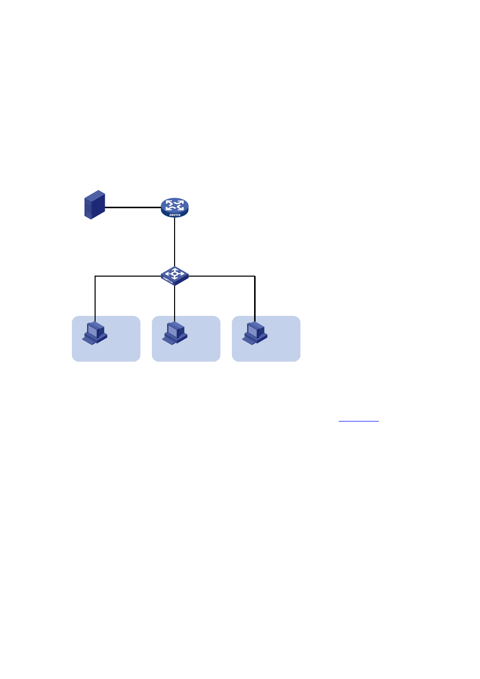
Host C are attached to GigabitEthernet 2/0/2 through GigabitEthernet 2/0/4 of Switch A
respectively.
z
The multicast source sends multicast data to multicast group 224.1.1.1. Host A, Host B,
and Host C are receivers of the multicast group.
z
Configure the sub-VLAN-based multicast VLAN feature so that Router A just sends
multicast data to Switch A through the multicast VLAN and Switch A forwards the traffic to
the receivers that belong to different user VLANs.
Network diagram
Figure 3-4 Network diagram for sub-VLAN-based multicast VLAN configuration
Source
Receiver
Host A
VLAN 2
GE2/0/2
GE2/0/3
GE2/0/4
Switch A
IGMP querier
Router A
GE2/0/1
1.1.1.2/24
GE2/0/2
10.110.1.1/24
1.1.1.1/24
Receiver
Host B
VLAN 3
Receiver
Host C
VLAN 4
GE2/0/1
Configuration procedure
1) Configure
IP
addresses
Configure an IP address and subnet mask for each interface as per
. The detailed
configuration steps are omitted here.
2) Configure Router A
# Enable IP multicast routing, enable PIM-DM on each interface and enable IGMP on the
host-side interface GigabitEthernet 2/0/2.
<RouterA> system-view
[RouterA] multicast routing-enable
[RouterA] interface gigabitethernet 2/0/1
[RouterA-GigabitEthernet2/0/1] pim dm
[RouterA-GigabitEthernet2/0/1] quit
[RouterA] interface gigabitethernet 2/0/2
[RouterA-GigabitEthernet2/0/2] pim dm
[RouterA-GigabitEthernet2/0/2] igmp enable
3) Configure Switch A
# Enable IGMP Snooping globally.
<SwitchA> system-view
[SwitchA] igmp-snooping