Igmp snooping querier configuration example, Network requirements, Configuration procedure – H3C Technologies H3C S7500E Series Switches User Manual
Page 65
2-33
IGMP Snooping Querier Configuration Example
Network requirements
z
As shown in
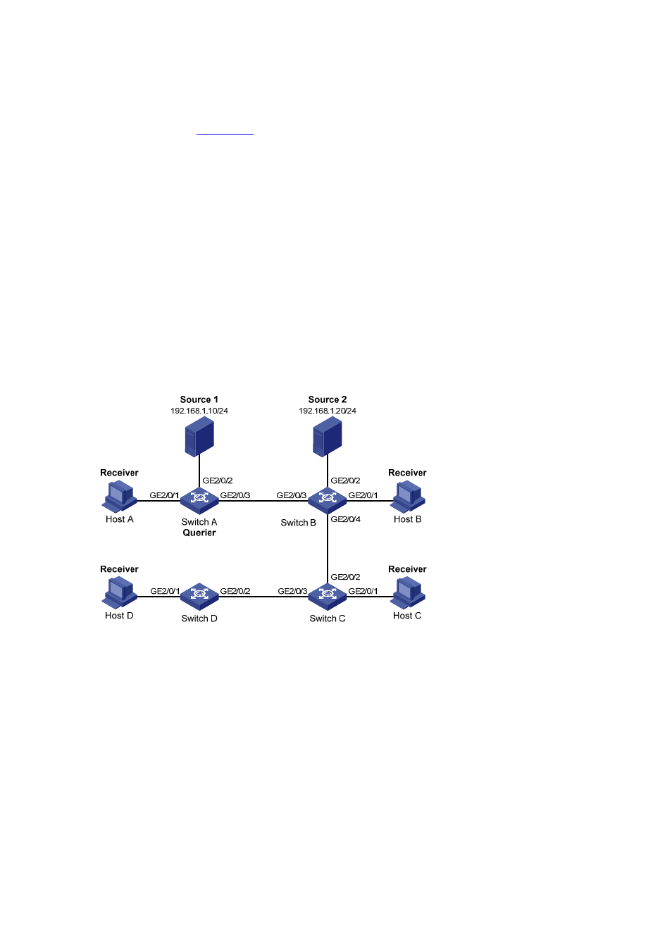
, in a Layer 2–only network environment, two multicast sources
Source 1 and Source 2 send multicast data to multicast groups 224.1.1.1 and 225.1.1.1
respectively, Host A and Host C are receivers of multicast group 224.1.1.1, while Host B
and Host D are receivers of multicast group 225.1.1.1.
z
All the receivers are running IGMPv2, and all the switches need to run IGMP snooping
version 2. Switch A, which is close to the multicast sources, is chosen as the
IGMP-Snooping querier.
z
To prevent flooding of unknown multicast traffic within the VLAN, it is required to configure
all the switches to drop unknown multicast data packets.
z
Because a switch does not enlist a port that has heard an IGMP query with a source IP
address of 0.0.0.0 (default) as a dynamic router port, configure a non-all-zero IP address
as the source IP address of IGMP queries to ensure normal creation of Layer 2 multicast
forwarding entries.
Figure 2-6 Network diagram for IGMP snooping querier configuration
Configuration procedure
1) Configure
switch
A
# Enable IGMP snooping globally.
<SwitchA> system-view
[SwitchA] igmp-snooping
[SwitchA-igmp-snooping] quit
# Create VLAN 100 and assign GigabitEthernet 2/0/1 through GigabitEthernet 2/0/3 to the
VLAN.
[SwitchA] vlan 100
[SwitchA-vlan100] port gigabitethernet 2/0/1 to gigabitethernet 2/0/3
# Enable IGMP snooping and the function of dropping unknown multicast traffic in VLAN 100.
[SwitchA-vlan100] igmp-snooping enable