Mbgp configuration example, Network requirements, Configuration procedure – H3C Technologies H3C S7500E Series Switches User Manual
Page 254
8-20
MBGP Configuration Example
Network requirements
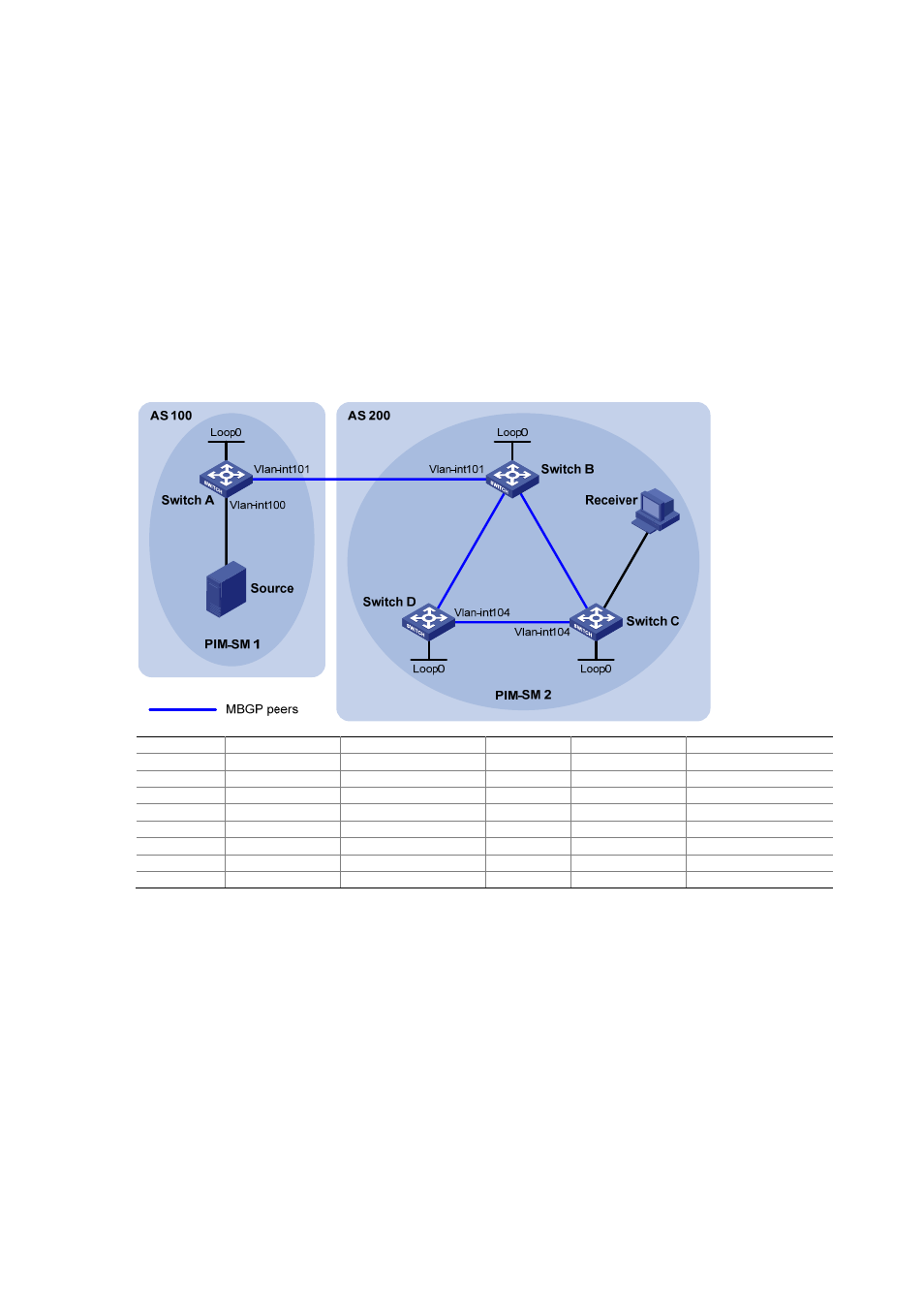
As shown in the following figure:
z
PIM-SM 1 is in AS 100 and PIM-SM 2 is in AS 200. OSPF is the IGP in the two ASs, and MBGP
runs between the two ASs to exchange multicast route information.
z
The multicast source belongs to PIM-SM 1, and the receiver belongs to PIM-SM 2.
z
It is required that the respective Loopback 0 of Switch A and Switch B be configured as the
C-BSR and C-RP of the respective PIM-SM domains.
z
Router A and Router B establishes an MSDP peer relationship through MBGP.
Figure 8-1 Network diagram for MBGP configuration
V
la
n
-in
t1
0
2
V
la
n
-i
n
t1
0
3
V
la
n
-i
n
t1
0
3
V
la
n
-in
t1
0
2
V
la
n
-i
n
t2
0
0
Device Interface
IP
address
Device Interface
IP
address
Source -
10.110.1.100/24 Switch C
Vlan-int200
10.110.2.1/24
Switch A
Vlan-int100
10.110.1.1/24
Vlan-int102
192.168.2.2/24
Vlan-int101
192.168.1.1/24
Vlan-int104
192.168.4.1/24
Loop0
1.1.1.1/32 Loop0
3.3.3.3/32
Switch B
Vlan-int101
192.168.1.2/24
Switch D
Vlan-int103
192.168.3.2/24
Vlan-int102
192.168.2.1/24
Vlan-int104
192.168.4.2/24
Vlan-int103
192.168.3.1/24
Loop0
4.4.4.4/32
Loop0
2.2.2.2/32
Configuration procedure
1) Configure IP addresses for interfaces as shown in the above figure (omitted).
2) Configure OSPF (omitted).
3) Enable IP multicast routing, PIM-SM and IGMP, and configure a PIM-SM domain border.
# Enable IP multicast routing on Switch A, and enable PIM-SM on each interface.
<SwitchA> system-view
[SwitchA] multicast routing-enable
[SwitchA] interface vlan-interface 100
[SwitchA-Vlan-interface100] pim sm
[SwitchA-Vlan-interface100] quit
[SwitchA] interface vlan-interface 101
[SwitchA-Vlan-interface101] pim sm