Network diagram, Configuration procedure – H3C Technologies H3C S7500E Series Switches User Manual
Page 230
7-29
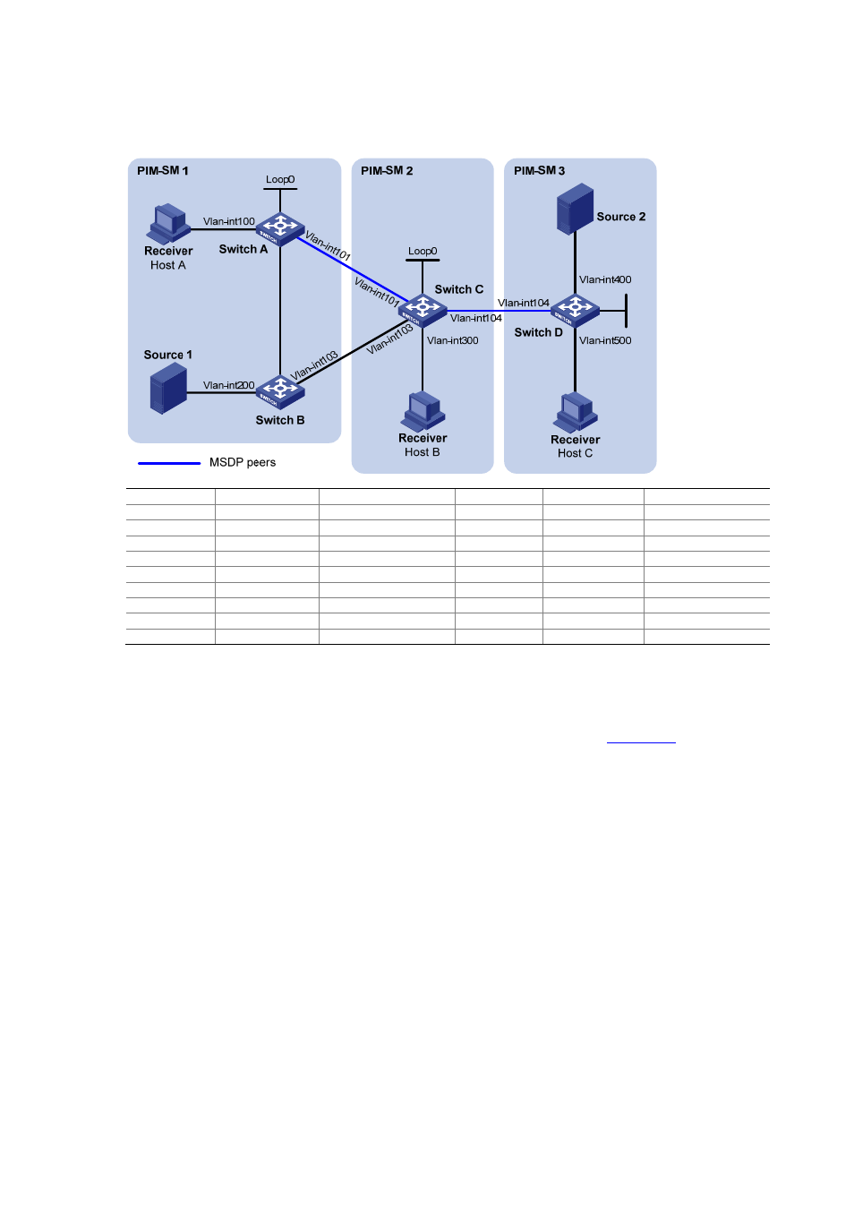
Network diagram
Figure 7-8 Network diagram for SA message filtering configuration
Loop0
V
lan-int102
Vlan-
int1
02
Device Interface IP
address
Device Interface IP
address
Source 1
—
10.110.3.100/24
Switch C
Vlan-int300
10.110.4.1/24
Source 2
—
10.110.6.100/24
Vlan-int104
10.110.5.1/24
Switch A
Vlan-int100
10.110.1.1/24
Vlan-int101
192.168.1.2/24
Vlan-int102
10.110.2.1/24
Vlan-int103
192.168.2.2/24
Vlan-int101
192.168.1.1/24
Loop0
2.2.2.2/32
Loop0
1.1.1.1/32
Switch
D
Vlan-int400 10.110.6.1/24
Switch B
Vlan-int200
10.110.3.1/24
Vlan-int500
10.110.7.1/24
Vlan-int102
10.110.2.2/24
Vlan-int104
10.110.5.2/24
Vlan-int103
192.168.2.1/24
Loop0
3.3.3.3/32
Configuration Procedure
1) Configure IP addresses and unicast routing
Configure the IP address and subnet mask for each interface as per
. The detailed
configuration steps are omitted here.
Configure OSPF for interoperation among the switches. Ensure the network-layer interoperation within
and between the PIM-SM domains and ensure dynamic update of routing information among the
switches by leveraging unicast routing. The detailed configuration steps are omitted here.
2) Enable IP multicast routing, PIM-SM and IGMP, and configure a PIM domain border
# On Switch A, enable IP multicast routing, enable PIM-SM on each interface, and enable IGMP on
the host-side interface, VLAN-interface 100.
<SwitchA> system-view
[SwitchA] multicast routing-enable
[SwitchA] interface vlan-interface 100
[SwitchA-Vlan-interface100] igmp enable
[SwitchA-Vlan-interface100] pim sm
[SwitchA-Vlan-interface100] quit
[SwitchA] interface vlan-interface 101
[SwitchA-Vlan-interface101] pim sm
[SwitchA-Vlan-interface101] quit
[SwitchA] interface vlan-interface 102