Configuration procedure – H3C Technologies H3C S7500E Series Switches User Manual
Page 305
10-9
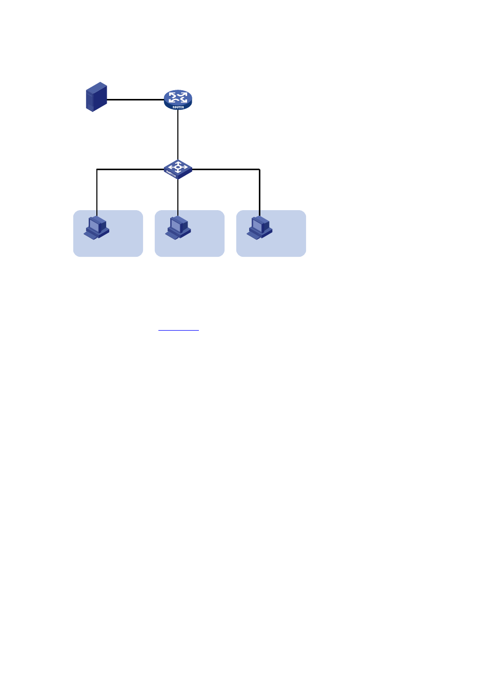
Figure 10-4 Network diagram for sub-VLAN-based IPv6 multicast VLAN configuration
Source
Receiver
Host A
VLAN 2
GE2/0/2
GE2/0/3
GE2/0/4
Switch A
MLD querier
Router A
GE2/0/1
1:2/64
GE2/0/2
2001::1/64
1::1/64
Receiver
Host B
VLAN 3
Receiver
Host C
VLAN 4
GE2/0/1
Configuration procedure
1) Enable IPv6 forwarding and configure IPv6 addresses
Enable IPv6 forwarding on each device and configure an IPv6 address and address prefix for
each interface as per
. The detailed configuration steps are omitted here.
2) Configure Router A
# Enable IPv6 multicast routing, enable IPv6 PIM-DM on each interface and enable MLD on the
host-side interface GigabitEthernet 2/0/2.
<RouterA> system-view
[RouterA] multicast ipv6 routing-enable
[RouterA] interface gigabitethernet 2/0/1
[RouterA-GigabitEthernet2/0/1] pim ipv6 dm
[RouterA-GigabitEthernet2/0/1] quit
[RouterA] interface gigabitethernet 2/0/2
[RouterA-GigabitEthernet2/0/2] pim ipv6 dm
[RouterA-GigabitEthernet2/0/2] mld enable
3) Configure Switch A
# Enable MLD Snooping globally.
<SwitchA> system-view
[SwitchA] mld-snooping
[SwitchA-mld-snooping] quit
# Create VLAN 2 and assign GigabitEthernet 2/0/2 to this VLAN.
[SwitchA] vlan 2
[SwitchA-vlan2] port gigabitethernet 2/0/2
[SwitchA-vlan2] quit
The configuration for VLAN 3 and VLAN 4 is similar to the configuration for VLAN 2.
# Create VLAN 10, assign GigabitEthernet 2/0/1 to this VLAN and enable MLD Snooping in the
VLAN.
[SwitchA] vlan 10