Mstp basic concepts – H3C Technologies H3C S5560 Series Switches User Manual
Page 104
Advertising
70
MSTP basic concepts
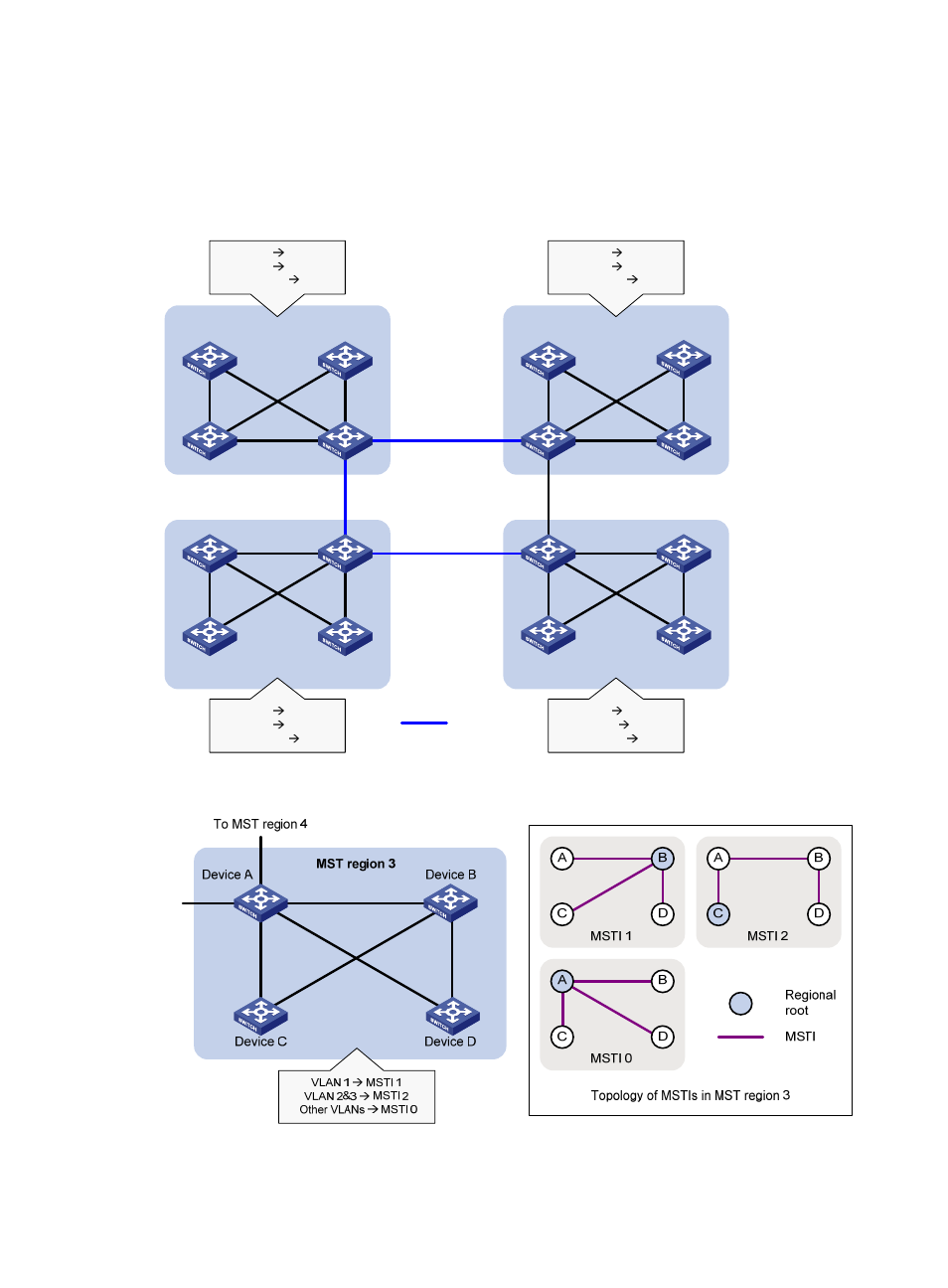
shows a switched network that comprises four MST regions, each MST region comprising four
shows the networking topology of MST region 3.
Figure 23 Basic concepts in MSTP
Figure 24 Network diagram and topology of MST region 3
MST region 1
MST region 2
MST region 3
MST region 4
VLAN 1
MSTI 1
VLAN 2
MSTI 2
Other VLANs
MSTI 0
VLAN 1
MSTI 1
VLAN 2
MSTI 2
Other VLANs
MSTI 0
VLAN 1
MSTI 1
VLAN 2
MSTI 2
Other VLANs
MSTI 0
VLAN 1
MSTI 1
VLAN 2&3
MSTI 2
Other VLANs
MSTI 0
CST
T
o
MST regi
on 2
Advertising
This manual is related to the following products: