Configuration procedure – H3C Technologies H3C S5560 Series Switches User Manual
Page 176
142
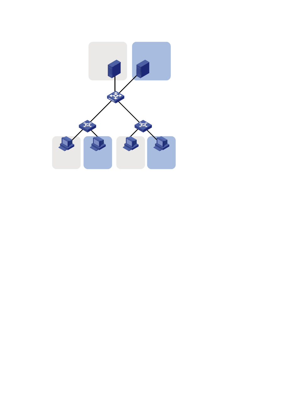
Figure 44 Network diagram
Configuration procedure
In this example, L2 Switch A and L2 Switch B use the factory configuration.
1.
Configure Device:
# Create VLAN 100, and configure the description for VLAN 100 as protocol VLAN for IPv4.
<Device> system-view
[Device] vlan 100
[Device-vlan100] description protocol VLAN for IPv4
# Assign GigabitEthernet 1/0/11 to VLAN 100.
[Device-vlan100] port gigabitethernet 1/0/11
[Device-vlan100] quit
# Create VLAN 200, and configure the description for VLAN 200 as protocol VLAN for IPv6.
[Device] vlan 200
[Device-vlan200] description protocol VLAN for IPv6
# Assign GigabitEthernet 1/0/12 to VLAN 200.
[Device-vlan200] port gigabitethernet 1/0/12
# Configure VLAN 200 as a protocol-based VLAN, and create an IPv6 protocol template with the
index 1 for VLAN 200.
[Device-vlan200] protocol-vlan 1 ipv6
[Device-vlan200] quit
# Configure VLAN 100 as a protocol-based VLAN, and create an IPv4 protocol template with the
index 1 for VLAN 100.
[Device] vlan 100
[Device-vlan100] protocol-vlan 1 ipv4
# Create an ARP protocol template with the index 2 for VLAN 100. (In Ethernet II encapsulation,
the protocol type ID for ARP is 0x0806.)
GE1/0/2
GE1/0/1
GE1/0/11
GE1/0/12
IPv4 Host A
IPv4 Host B
IPv6 Host A
IPv6 Host B
IPv4 server
IPv6 server
Device
L2 Switch A
L2 Switch B
VLAN 100
VLAN 100
VLAN 100
VLAN 200
VLAN 200
VLAN 200