Network requirements, Configuration procedure – H3C Technologies H3C S5560 Series Switches User Manual
Page 264
230
One-to-two and two-to-two VLAN mapping configuration
example
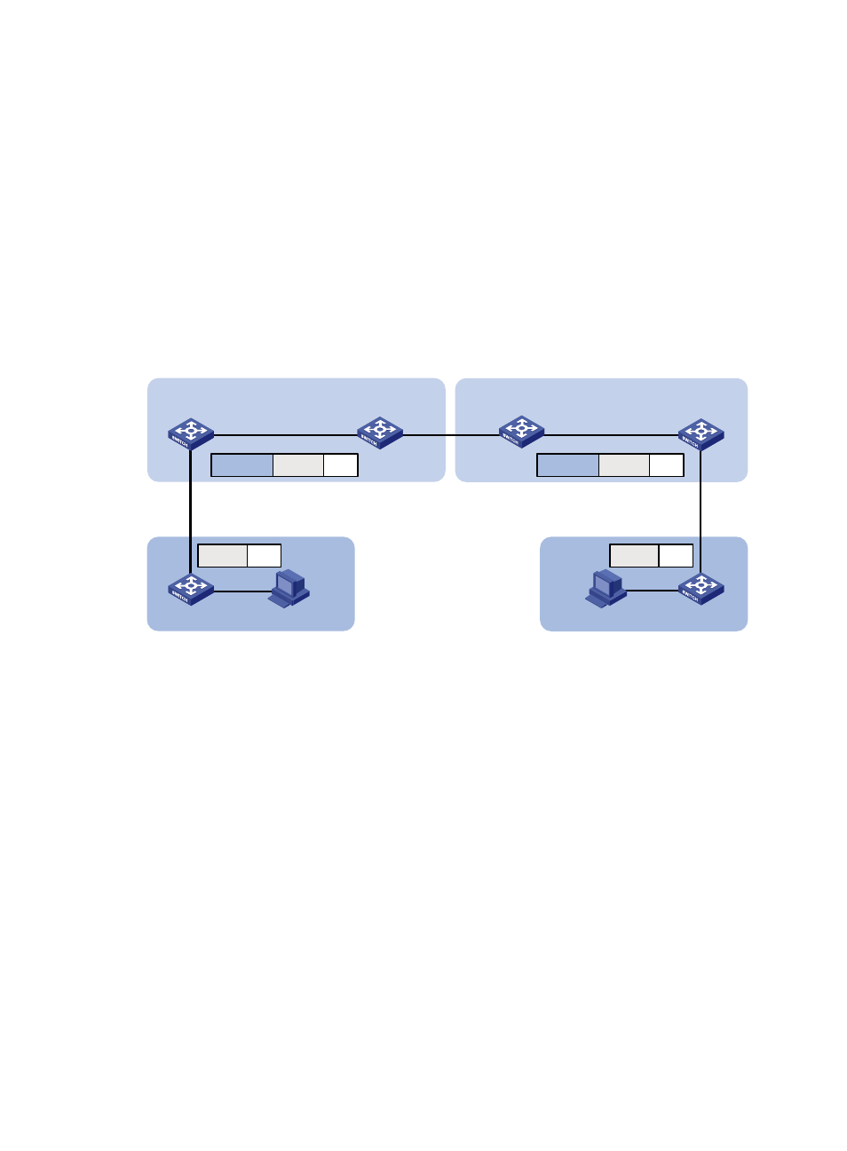
Network requirements
As shown in
:
•
Two VPN A branches, Site 1 and Site 2, are in VLAN 5 and VLAN 6, respectively.
•
The two sites use different VPN access services from different service providers, SP 1 and SP 2.
•
SP 1 assigns VLAN 100 to Site 1 and Site 2. SP 2 assigns VLAN 200 to Site 1 and Site 2.
Configure one-to-two VLAN mappings and a two-to-two VLAN mapping to enable the two branches to
communicate across networks SP 1 and SP 2.
Figure 70 Network diagram
Configuration procedure
1.
Configure PE 1:
# Configure a one-to-two VLAN mapping on the customer-side port GigabitEthernet 1/0/1 to add
SVLAN tag 100 to traffic from VLAN 5.
<PE1> system-view
[PE1] interface gigabitethernet 1/0/1
[PE1-GigabitEthernet1/0/1] vlan mapping nest single 5 nested-vlan 100
# Configure GigabitEthernet 1/0/1 as a hybrid port. Assign the port to VLAN 5 and VLAN 100
as a tagged member and an untagged member, respectively.
[PE1-GigabitEthernet1/0/1] port link-type hybrid
[PE1-GigabitEthernet1/0/1] port hybrid vlan 5 tagged
[PE1-GigabitEthernet1/0/1] port hybrid vlan 100 untagged
[PE1-GigabitEthernet1/0/1] quit
# Configure the network-side port GigabitEthernet 1/0/2 as a trunk port, and assign the port to
VLAN 100.
[PE1] interface gigabitethernet 1/0/2
[PE1-GigabitEthernet1/0/2] port link-type trunk
[PE1-GigabitEthernet1/0/2] port trunk permit vlan 100
[PE1-GigabitEthernet1/0/2] quit
PE 1
SP 1
SP 2
PE 2
PE 3
PE 4
GE1/0/1
GE1/0/2
GE1/0/1
GE1/0/2
GE1/0/1
GE1/0/2
GE1/0/1
GE1/0/2
VPN A
Site 1
CE 1
CE 2
VPN A
Site 2
Data
VLAN 5
Data
VLAN 100
VLAN 5
Data
VLAN 200
VLAN 6
Data
VLAN 6