Example of stp calculation – H3C Technologies H3C S5560 Series Switches User Manual
Page 98
64
Example of STP calculation
provides an example showing how the STP algorithm works.
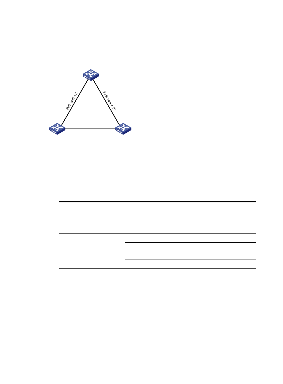
Figure 21 The STP algorithm
As shown in
, the priority values of Device A, Device B, and Device C are 0, 1, and 2,
respectively. The path costs of links among the three devices are 5, 10, and 4.
1.
Device state initialization.
In
, each configuration BPDU contains the following fields: root bridge ID, root path cost,
designated bridge ID, and designated port ID.
Table 7 Initial state of each device
Device
Port name
Configuration BPDU on the
port
Device A
Port A1
{0, 0, 0, Port A1}
Port A2
{0, 0, 0, Port A2}
Device B
Port B1
{1, 0, 1, Port B1}
Port B2
{1, 0, 1, Port B2}
Device C
Port C1
{2, 0, 2, Port C1}
Port C2
{2, 0, 2, Port C2}
2.
Configuration BPDUs comparison on each device.
In
, each configuration BPDU contains the following fields: root bridge ID, root path cost,
designated bridge ID, and designated port ID.
Device A
Priority = 0
Device B
Priority = 1
Device C
Priority = 2
Port A1
Port A2
Port B1
Port B2
Port C1
Port C2
Path cost = 4