Pvst configuration example, Network requirements – H3C Technologies H3C S5560 Series Switches User Manual
Page 142
108
0 GigabitEthernet1/0/2 ALTE DISCARDING NONE
0 GigabitEthernet1/0/3 ALTE DISCARDING NONE
3 GigabitEthernet1/0/1 ROOT FORWARDING NONE
3 GigabitEthernet1/0/2 ALTE DISCARDING NONE
4 GigabitEthernet1/0/3 ROOT FORWARDING NONE
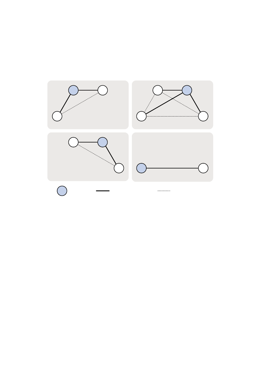
Based on the output, you can draw each MSTI mapped to each VLAN, as shown in
.
Figure 32 MSTIs mapped to different VLANs
PVST configuration example
Network requirements
As shown in
, Device A and Device B work at the distribution layer, and Device C and Device
D work at the access layer.
Configure PVST to meet the following requirements:
•
Packets of a VLAN are forwarded along the spanning trees of the VLAN.
•
VLAN 10, VLAN 20, and VLAN 30 are terminated on the distribution layer devices, and VLAN 40
is terminated on the access layer devices.
•
The root bridge of VLAN 10 and VLAN 20 is Device A.
•
The root bridge of VLAN 30 is Device B.
•
The root bridge of VLAN 40 is Device C.
A
B
A
B
C
D
C
B
C
MSTI 1 mapped to VLAN 10
A
D
D
Root bridge
Normal link
Blocked link
MSTI 3 mapped to VLAN 30
MSTI 0 mapped to VLAN 20
MSTI 4 mapped to VLAN 40