Network requirements, Configuration procedure – H3C Technologies H3C S5560 Series Switches User Manual
Page 83
49
--------------------------------------------------------------------------------
GE1/0/1 S 32768 1 {ACDEF}
GE1/0/2 S 32768 1 {ACDEF}
GE1/0/3 S 32768 1 {ACDEF}
Remote:
Actor Partner Priority Oper-Key SystemID Flag
--------------------------------------------------------------------------------
GE1/0/1 1 32768 1 0x8000, 000f-e267-57ad {ACDEF}
GE1/0/2 2 32768 1 0x8000, 000f-e267-57ad {ACDEF}
GE1/0/3 3 32768 1 0x8000, 000f-e267-57ad {ACDEF}
The output shows that:
•
Link aggregation group 1 is a Layer 2 dynamic aggregation group.
•
The aggregation group contains three Selected ports.
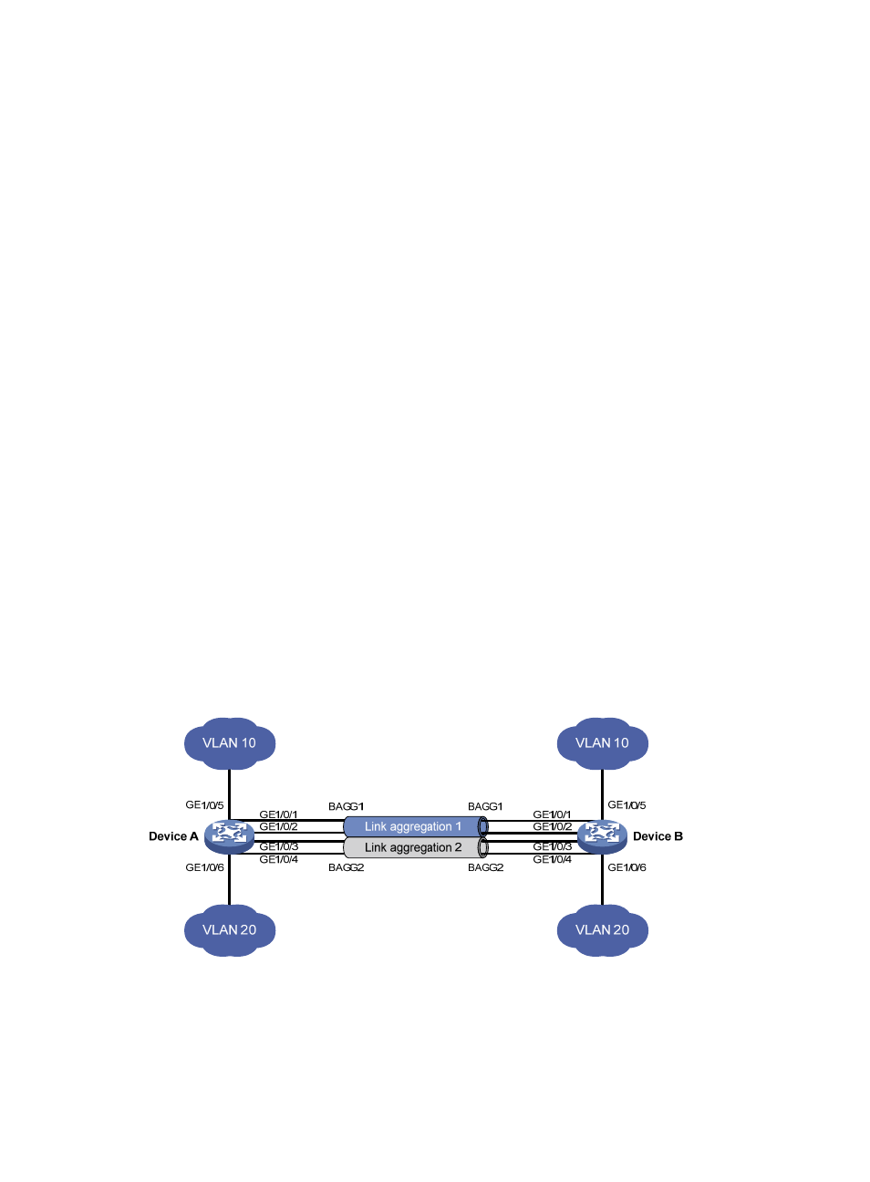
Layer 2 aggregation load sharing configuration example
Network requirements
On the network shown in
, perform the following tasks:
•
Configure two Layer 2 static aggregation groups 1 and 2 on Device A and Device B, respectively.
•
Enable VLAN 10 at one end of the aggregate link to communicate with VLAN 10 at the other end.
•
Enable VLAN 20 at one end of the aggregate link to communicate with VLAN 20 at the other end.
•
Configure link aggregation groups 1 and 2 to load share traffic across aggregation group member
ports.
{
Configure link aggregation group 1 to load share packets based on source MAC addresses.
{
Configure link aggregation group 2 to load share packets based on destination MAC
addresses.
Figure 14 Network diagram
Configuration procedure
1.
Configure Device A:
# Create VLAN 10, and assign the port GigabitEthernet 1/0/5 to VLAN 10.
<DeviceA> system-view