Configuration procedure, Verifying the configuration – H3C Technologies H3C S5560 Series Switches User Manual
Page 182
148
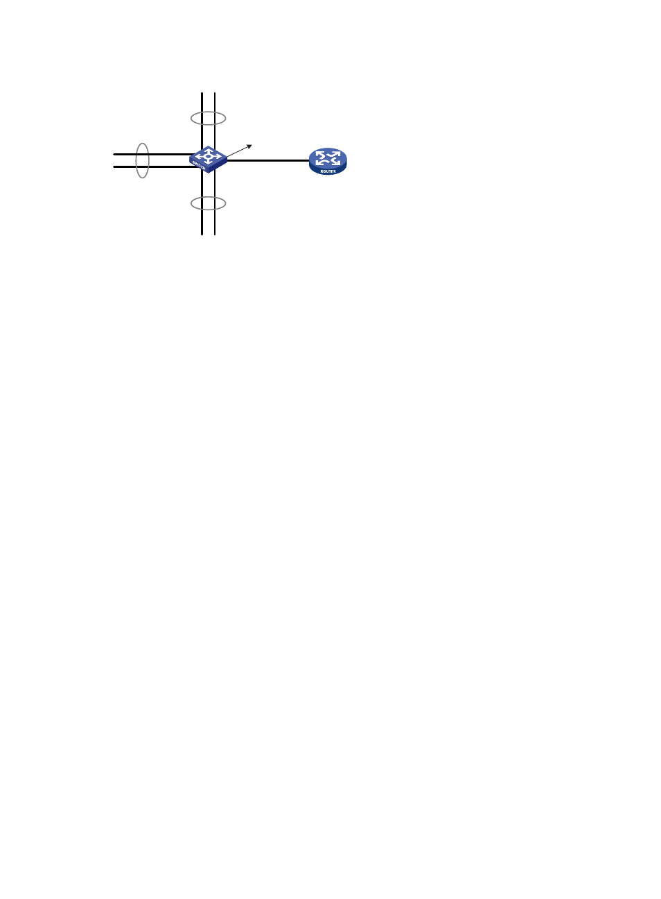
Figure 45 Network diagram
Configuration procedure
# Create VLAN 10, and configure its VLAN interface IP address as 10.1.1.1/24.
<DeviceA> system-view
[DeviceA] vlan 10
[DeviceA-vlan10] quit
[DeviceA] interface vlan-interface 10
[DeviceA-Vlan-interface10] ip address 10.1.1.1 255.255.255.0
# Enable local proxy ARP.
[DeviceA-Vlan-interface10] local-proxy-arp enable
[DeviceA-Vlan-interface10] quit
# Create VLAN 2, and assign GigabitEthernet 1/0/1 and GigabitEthernet 1/0/2 to the VLAN.
[DeviceA] vlan 2
[DeviceA-vlan2] port gigabitethernet 1/0/1 gigabitethernet 1/0/2
[DeviceA-vlan2] quit
# Create VLAN 3, and assign GigabitEthernet 1/0/3 and GigabitEthernet 1/0/4 to the VLAN.
[DeviceA] vlan 3
[DeviceA-vlan3] port gigabitethernet 1/0/3 gigabitethernet 1/0/4
[DeviceA-vlan3] quit
# Create VLAN 5, and assign GigabitEthernet 1/0/5 and GigabitEthernet 1/0/6 to the VLAN.
[DeviceA] vlan 5
[DeviceA-vlan5] port gigabitethernet 1/0/5 gigabitethernet 1/0/6
[DeviceA-vlan5] quit
# Configure VLAN 10 as a super VLAN, and associate sub-VLANs 2, 3, and 5 with the super VLAN.
[DeviceA] vlan 10
[DeviceA-vlan10] supervlan
[DeviceA-vlan10] subvlan 2 3 5
[DeviceA-vlan10] quit
[DeviceA] quit
Verifying the configuration
# Display information about super VLAN 10 and its associated sub-VLANs.
GE1/0/1
GE1/0/2
GE1/0/3
GE1/0/4
GE1/0/5
GE1/0/6
Vlan-int10
10.1.1.1/24
VLAN 2
VLAN 5
VLAN 3
Device A
Device B