Verifying the configuration, Network requirements – H3C Technologies H3C S5560 Series Switches User Manual
Page 89
55
[DeviceA-GigabitEthernet1/0/3] port link-aggregation group 1
[DeviceA-GigabitEthernet1/0/3] quit
2.
Configure Device B in the same way Device A is configured. (Details not shown.)
Verifying the configuration
# Display detailed information about all aggregation groups on Device A.
[DeviceA] display link-aggregation verbose
Loadsharing Type: Shar -- Loadsharing, NonS -- Non-Loadsharing
Port Status: S -- Selected, U -- Unselected, I -- Individual
Flags: A -- LACP_Activity, B -- LACP_Timeout, C -- Aggregation,
D -- Synchronization, E -- Collecting, F -- Distributing,
G -- Defaulted, H -- Expired
Aggregate Interface: Route-Aggregation1
Aggregation Mode: Dynamic
Loadsharing Type: Shar
System ID: 0x8000, 000f-e267-6c6a
Local:
Port Status Priority Oper-Key Flag
--------------------------------------------------------------------------------
GE1/0/1 S 32768 1 {ACDEF}
GE1/0/2 S 32768 1 {ACDEF}
GE1/0/3 S 32768 1 {ACDEF}
Remote:
Actor Partner Priority Oper-Key SystemID Flag
--------------------------------------------------------------------------------
GE1/0/1 1 32768 1 0x8000, 000f-e267-57ad {ACDEF}
GE1/0/2 2 32768 1 0x8000, 000f-e267-57ad {ACDEF}
GE1/0/3 3 32768 1 0x8000, 000f-e267-57ad {ACDEF}
The output shows that:
•
Link aggregation group 1 is a non-load-shared Layer 3 dynamic aggregation group.
•
The aggregation group contains three Selected ports.
Layer 3 edge aggregate interface configuration example
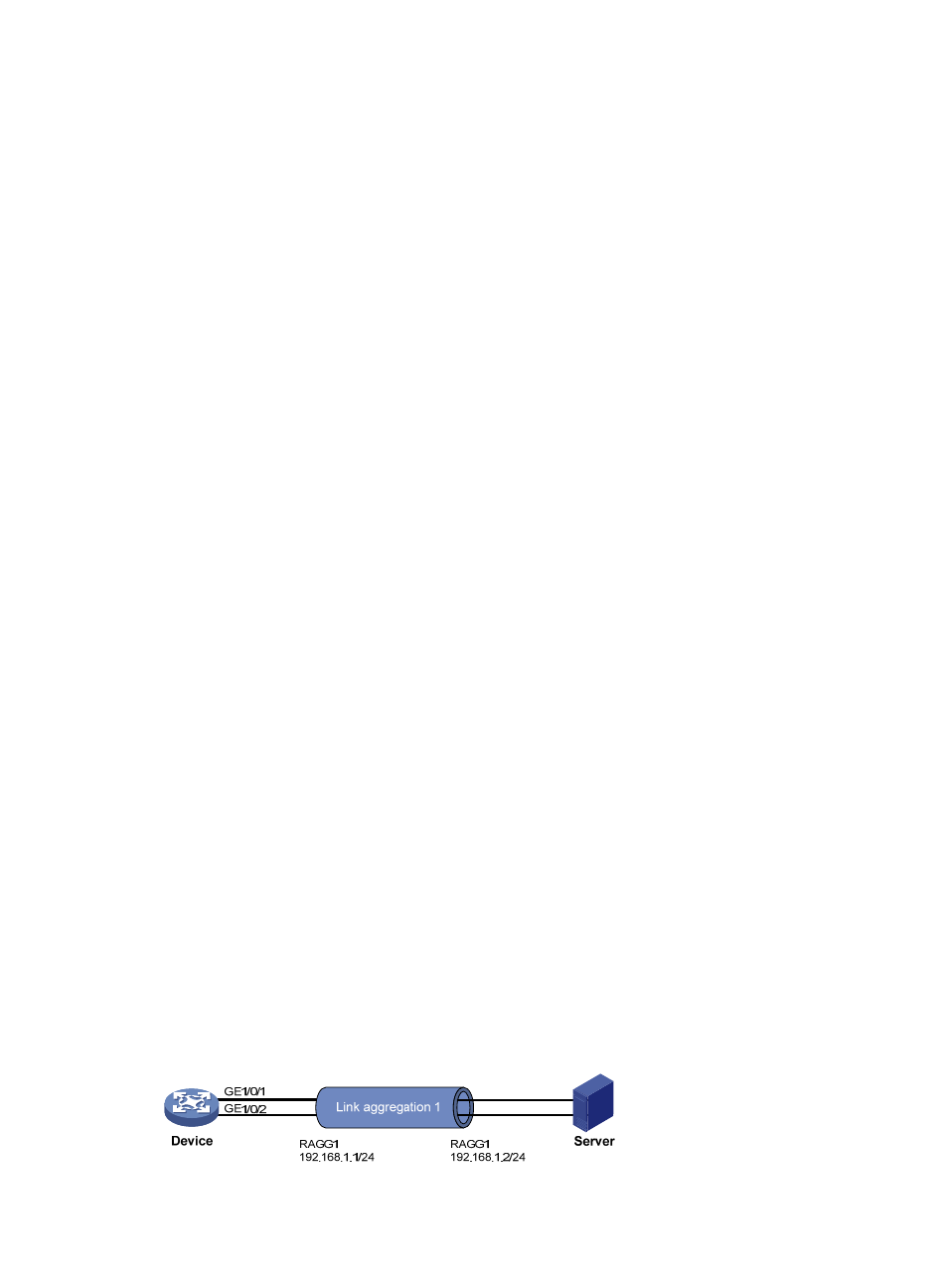
Network requirements
As shown in
, a Layer 3 dynamic aggregation group is configured on the device. The server is
not configured with dynamic link aggregation.
Configure an edge aggregate interface so that both GigabitEthernet 1/0/1 and GigabitEthernet 1/0/2
can forward traffic to improve link reliability.
Figure 18 Network diagram