Configuration procedure – H3C Technologies H3C S5560 Series Switches User Manual
Page 200
166
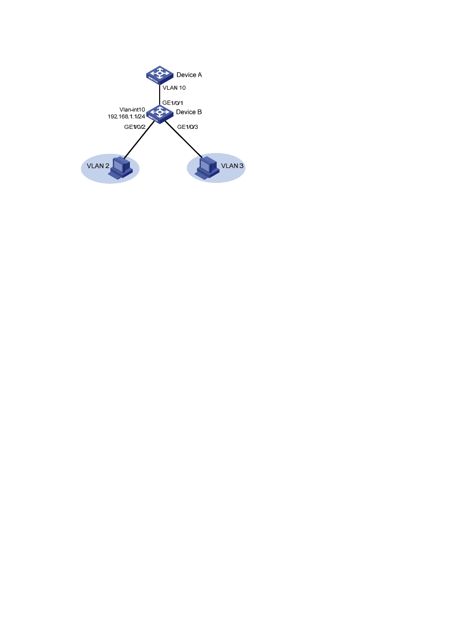
Figure 50 Network diagram
Configuration procedure
# Create VLAN 2 and VLAN 3.
<DeviceB> system-view
[DeviceB] vlan 2 to 3
# Configure VLAN 10 as a primary VLAN, and associate VLAN 2 and VLAN 3 with primary VLAN 10
as secondary VLANs.
[DeviceB] vlan 10
[DeviceB-vlan10] private-vlan primary
[DeviceB-vlan10] private-vlan secondary 2 3
[DeviceB-vlan10] quit
# Configure the uplink port GigabitEthernet 1/0/1 as a promiscuous port of VLAN 10.
[DeviceB] interface gigabitethernet 1/0/1
[DeviceB-GigabitEthernet1/0/1] port private-vlan 10 promiscuous
[DeviceB-GigabitEthernet1/0/1] quit
# Assign the downlink port GigabitEthernet 1/0/2 to VLAN 2, and configure the port as a host port.
[DeviceB] interface gigabitethernet 1/0/2
[DeviceB-GigabitEthernet1/0/2] port access vlan 2
[DeviceB-GigabitEthernet1/0/2] port private-vlan host
[DeviceB-GigabitEthernet1/0/2] quit
# Assign the downlink port GigabitEthernet 1/0/3 to VLAN 3, and configure the port as a host port.
[DeviceB] interface gigabitethernet 1/0/3
[DeviceB-GigabitEthernet1/0/3] port access vlan 3
[DeviceB-GigabitEthernet1/0/3] port private-vlan host
[DeviceB-GigabitEthernet1/0/3] quit
# Enable Layer 3 communication between secondary VLANs 2 and 3 that are associated with primary
VLAN 10.
[DeviceB] interface vlan-interface 10
[DeviceB-Vlan-interface10] private-vlan secondary 2 3
# Assign the IP address 192.168.1.1/24 to VLAN-interface 10.
[DeviceB-Vlan-interface10] ip address 192.168.1.1 255.255.255.0
# Enable local proxy ARP on VLAN-interface 10.
[DeviceB-Vlan-interface10] local-proxy-arp enable