Configuration procedure, Figure 57 network diagram, Configure device a: # enter mst region view – H3C Technologies H3C S5560 Series Switches User Manual
Page 225: Manually activate the mst region configuration, Globally enable the spanning tree feature
191
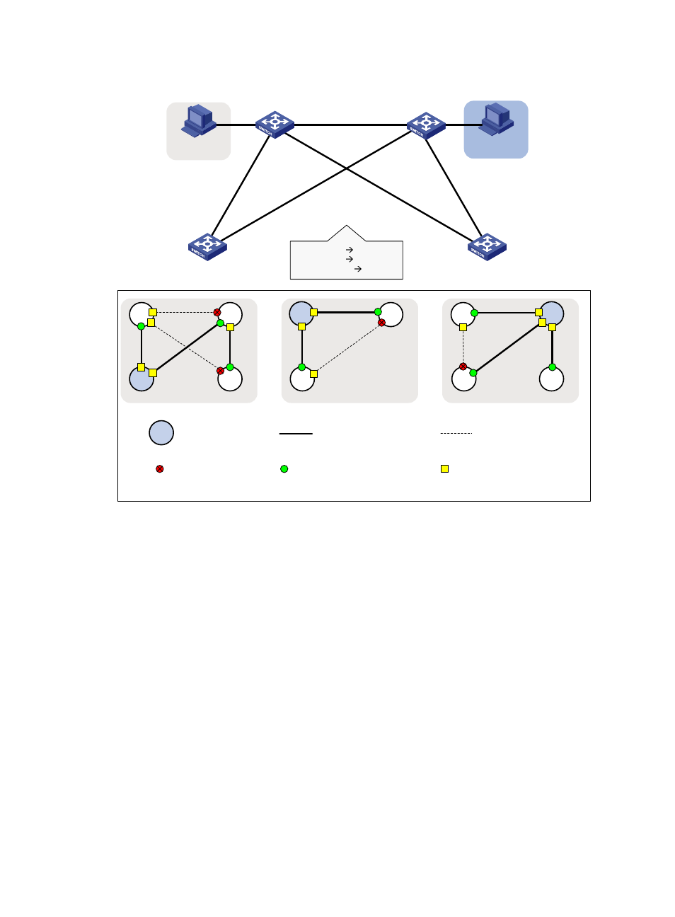
Figure 57 Network diagram
Configuration procedure
1.
Configure Device A:
# Enter MST region view.
<DeviceA> system-view
[DeviceA] stp region-configuration
# Configure the MST region name, VLAN-to-instance mappings, and revision level.
[DeviceA-mst-region] region-name example
[DeviceA-mst-region] instance 1 vlan 10
[DeviceA-mst-region] instance 2 vlan 20
[DeviceA-mst-region] revision-level 0
# Manually activate the MST region configuration.
[DeviceA-mst-region] active region-configuration
[DeviceA-mst-region] quit
# Configure Device A as the primary root bridge of MSTI 1.
[DeviceA] stp instance 1 root primary
# Globally enable the spanning tree feature.
[DeviceA] stp global enable
VLAN 20
Permit: all VLANs
Per
mit:
VL
AN
40
Pe
rm
it:
al
l V
LA
Ns
Permit: VLANs 20, 40
Permit: all VLANs
Device A
Device B
Device C
Device D
GE
1/0
/2
G
E
1
/0
/1
GE
1/0
/2
G
E
1
/0
/1
G
E
1
/0
/1
G
E
1
/0
/1
GE1/0/3
GE1/0/3
GE
1/0
/2
GE
1/0
/2
VLAN 10
MSTI 1
VLAN 20
MSTI 2
Other VLANs
MSTI 0
VLAN 10
MSTI 2
A
D
Blocked port
Root bridge
MSTI 1
B
MSTI 0
A
C
B
D
A
C
B
C
Topology of each MSTI
Root port
Designated port
Link not blocked
by spanning tree
Link blocked by
spanning tree