Mstp configuration example, Network requirements, Network diagram – H3C Technologies H3C WX6000 Series Access Controllers User Manual
Page 199: Configuration procedure
20-41
To do...
Use the command...
Remarks
View root bridge information of all MSTP
instances
display stp root
Available in any view
Clear the statistics information of MSTP
reset stp
[ interface interface-list ]
Available in user view
MSTP Configuration Example
Network requirements
Configure MSTP so that packets of different VLANs are forwarded along different spanning trees. The
specific configuration requirements are as follows:
z
All devices on the network are in the same MST region.
z
Packets of VLAN 10 are forwarded along MST region 1, those of VLAN 30 are forwarded along
MST instance 3, those of VLAN 40 are forwarded along MST instance 4, and those of VLAN 20 are
forwarded along MST instance 0.
z
AC A and AC B are convergence layer devices, while AC C and AC D are access layer devices.
VLAN 10 and VLAN 30 are terminated on the convergence layer devices, and VLAN 40 is
terminated on the access layer devices, so the root bridges of MST instance 1 and MST instance 3
are AC A and AC B respectively, while the root bridge of MST instance 4 is AC C.
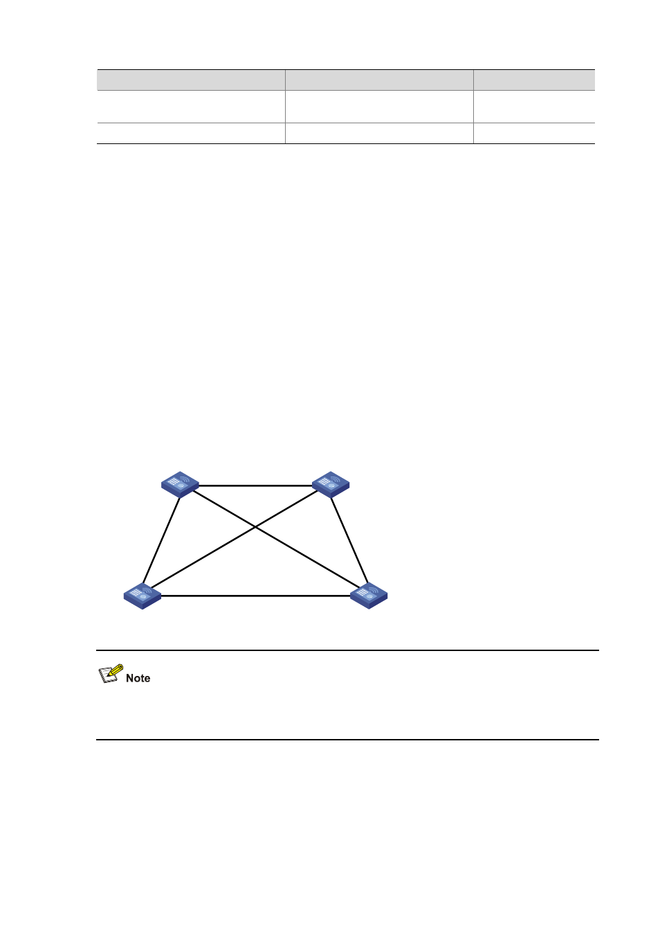
Network diagram
Figure 20-10
Network diagram for MSTP configuration
Permit:all VLAN
Permit:
VLAN 20,30
Permit:
VLAN 10,20
Permit:VLAN 20, 40
Permit:
VLAN 20,30
Permit:
VLAN 10,20
AC A
AC B
AC C
AC D
“Permit:“ beside each link in the figure is followed by the VLANs the packets of which are permitted to
pass this link.
Configuration procedure
1) Configuration on AC A
# Enter MST region view.
<AC A> system-view
[AC A] stp region-configuration