Igmp snooping querier configuration, Network requirements, Network diagram – H3C Technologies H3C WX6000 Series Access Controllers User Manual
Page 341: Configuration procedure
29-23
MAC group(s):
MAC group address:0100-5e01-0101
Host port(s):total 1 port.
GE0/0/2
As shown above, GigabitEthernet 0/0/3 of AC has become a static router port.
IGMP Snooping Querier Configuration
Network requirements
z
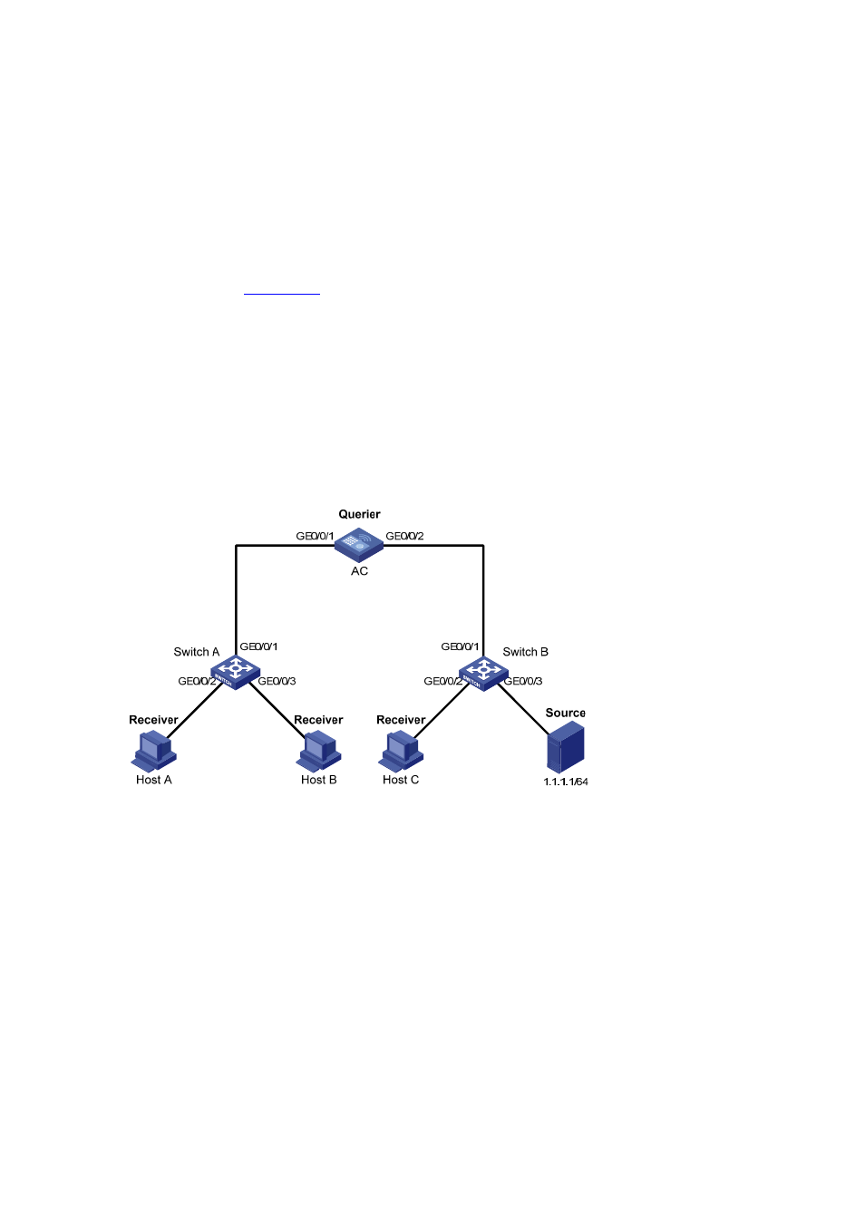
As shown in
, in a Layer-2-only network environment, Switch B is connected to the
multicast source (Source) through GigabitEthernet 0/0/3. At least one receiver is attached to
Switch A and Switch B respectively.
z
IGMPv2 is enabled on all the receivers. AC, Switch A, and Switch B run IGMP Snooping. AC acts
as the IGMP-Snooping querier.
z
Configure a non-all-zero IP address as the source IP address of IGMP queries to ensure normal
creation of multicast forwarding entries.
Network diagram
Figure 29-5
Network diagram for IGMP Snooping querier configuration
Configuration procedure
1) Configure AC
# Enable IGMP Snooping globally.
<AC> system-view
[AC] igmp-snooping
[AC-igmp-snooping] quit
# Create VLAN 100 and add GigabitEthernet 0/0/1 and GigabitEthernet 0/0/2 to VLAN 100.
[AC] vlan 100
[AC-vlan100] port GigabitEthernet 0/0/1 GigabitEthernet 0/0/2
# Enable IGMP Snooping in VLAN 100 and configure the IGMP-Snooping querier feature.
[AC-vlan100] igmp-snooping enable
[AC-vlan100] igmp-snooping querier
# Set the source IP address of IGMP general queries and group-specific queries to 192.168.1.1.