Network diagram, Configuration procedure – H3C Technologies H3C WX6000 Series Access Controllers User Manual
Page 372
34-3
z
GigabitEthernet 0/0/2 and GigabitEthernet 0/0/3 isolated at Layer 2 can implement Layer 3
communication.
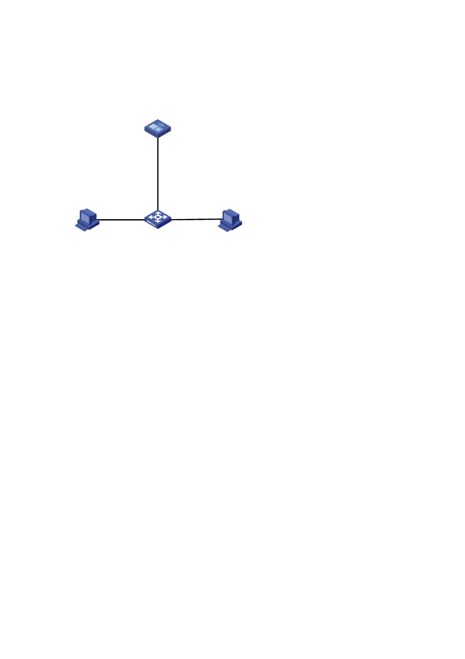
Network diagram
Figure 34-2
Network diagram for local proxy ARP between isolated ports
Switch
GE0/0/2
GE0/0/3
GE0/0/1
Host A
192.168.10.99/16
Host B
192.168.10.200/16
GE0/0/2
VLAN 2
Vlan-int2
192.168.10.100/16
AC
Configuration procedure
1) Configure
Switch
# Create VLAN 2 on Switch, on which GigabitEthernet 0/0/1, GigabitEthernet 0/0/2, and
GigabitEthernet 0/0/3 belong to VLAN 2. Host A and Host B are isolated and unable to exchange Layer
2 packets.
<Switch> system-view
[Switch] vlan 2
[Switch-vlan2] port gigabitethernet 0/0/1
[Switch-vlan2] port gigabitethernet 0/0/2
[Switch-vlan2] port gigabitethernet 0/0/3
[Switch-vlan2] quit
[Switch] interface gigabitethernet 0/0/2
[Switch-GigabitEthernet0/0/2] port-isolate enable
[Switch-GigabitEthernet0/0/2] quit
[Switch] interface gigabitethernet 0/0/3
[Switch-GigabitEthernet0/0/3] port-isolate enable
[Switch-GigabitEthernet0/0/3] quit
2) Configure
AC
# Configure an IP address of VLAN-interface 2.
[AC] vlan 2
[AC-vlan2] port gigabitethernet 0/0/2
[AC-vlan2] quit
[AC] interface vlan-interface 2
[AC-Vlan-interface2] ip address 192.168.10.100 255.255.0.0
Ping Host B on Host A to verify that the two hosts cannot be pinged through, which indicates they are
isolated at Layer 2.
# Configure local proxy ARP to let Host A and Host B communicate at Layer 3.
[AC-Vlan-interface2] local-proxy-arp enable
[AC-Vlan-interface2] quit