Ospf graceful restart configuration example, Network requirements, Network diagram – H3C Technologies H3C WX6000 Series Access Controllers User Manual
Page 284: Configuration procedure
25-50
OSPF Graceful Restart Configuration Example
Network requirements
z
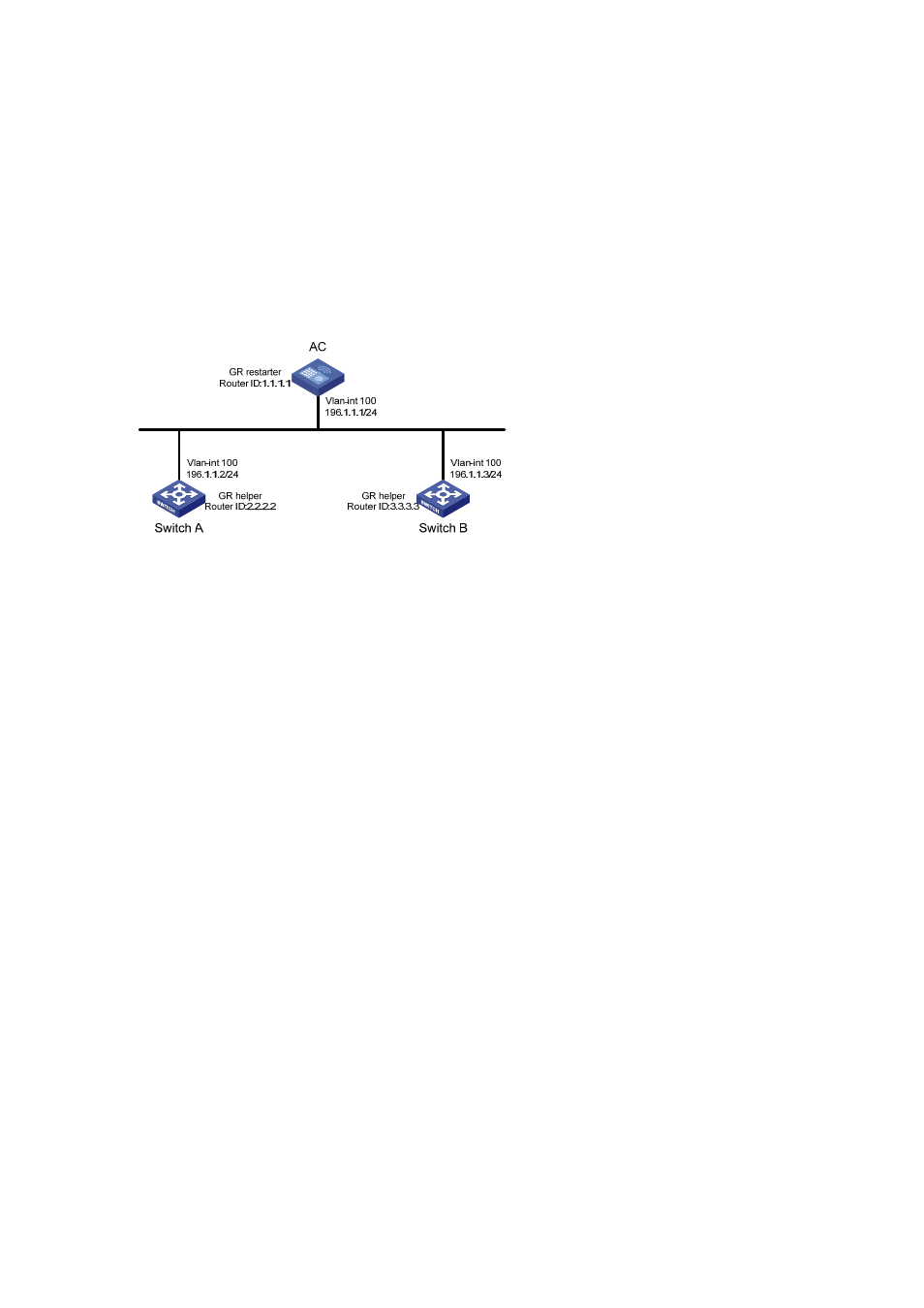
AC, Switch A and Switch B that belong to the same autonomous system and the same OSPF
routing domain are GR capable.
z
AC acts as the non IETF standard GR Restarter whereas Switch A and Switch B are the GR
Helpers and remain OOB synchronized with AC through the GR mechanism.
Network diagram
Figure 25-26
Network diagram for OSPF-based GR configuration
Configuration procedure
1) Configure
AC
<AC> system-view
[AC] interface vlan-interface 100
[AC-Vlan-interface100] ip address 192.1.1.1 255.255.255.0
[AC-Vlan-interface100] quit
[AC] router id 1.1.1.1
[AC] ospf 100
[AC-ospf-100] enable link-local-signaling
[AC-ospf-100] enable out-of-band-resynchronization
[AC-ospf-100] graceful-restart
[AC-ospf-100] area 0
[AC-ospf-100-area-0.0.0.0] network 192.1.1.0 0.0.0.255
[AC-ospf-100-area-0.0.0.0] return
2) Configure Switch A
<SwitchA> system-view
[SwitchA] acl number 2000
[SwitchA-acl-basic-2000] rule 10 permit source 192.1.1.1 0.0.0.0
[SwitchA-acl-basic-2000] quit
[SwitchA] interface vlan-interface 100
[SwitchA-Vlan-interface100] ip address 192.1.1.2 255.255.255.0
[SwitchA-Vlan-interface100] ospf dr-priority 0
[SwitchA-Vlan-interface100] quit
[SwitchA] router id 2.2.2.2
[SwitchA] ospf 100
[SwitchA-ospf-100] enable link-local-signaling
[SwitchA-ospf-100] enable out-of-band-resynchronization
[SwitchA-ospf-100] graceful-restart help 2000