Priority trust mode – H3C Technologies H3C WX3000 Series Unified Switches User Manual
Page 349
37-5
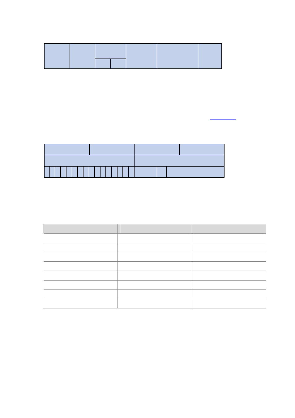
Figure 37-2
An Ethernet frame with an 802.1Q tag header
Length/Type
Data
6 bytes
6 bytes
4 bytes
2 bytes
46~1517 bytes
4 bytes
TPID
TCI
Source
Address
Destination
Address
802.1Q
header
FCS
(CRC-32)
As shown in the figure above, each host supporting 802.1Q protocol adds a 4-byte 802.1Q tag header
after the source address of the former Ethernet frame header when sending packets.
The 4-byte 802.1Q tag header consists of the tag protocol identifier (TPID, two bytes in length), whose
value is 0x8100, and the tag control information (TCI, two bytes in length).
describes the
detailed contents of an 802.1Q tag header.
Figure 37-3
802.1Q tag headers
Byte 1
TPID (Tag Protocol Identifier)
TCI (Tag Control Information)
Priority
cfi
VLAN ID
Byte 2
Byte 3
Byte 4
0
0 0 0
0
0 0
0
1
0
0 0
0 1
0 0
3 2
7
4
1 0
6 5
3 2
7
4
1 0
6 5
3 2
7
4
1 0
6 5
3 2
7
4
1 0
6 5
In the figure above, the priority field (three bits in length) in TCI is 802.1p priority (also known as CoS
precedence), which ranges from 0 to 7.
Table 37-3
Description on 802.1p priority
802.1p priority (decimal)
802.1p priority (binary)
Description
0 000
best-effort
1 001
background
2 010
spare
3 011
excellent-effort
4 100
controlled-load
5 101
video
6 110
voice
7 111
network-management
The precedence is called 802.1p priority because the related applications of this precedence are
defined in detail in the 802.1p specifications.
Priority Trust Mode
A device can assign different types of precedence to the packets it receives as configured, such as
802.1p precedence, DSCP precedence, local precedence, and drop precedence.
Among the above-mentioned precedence types: