H3C Technologies H3C WX3000 Series Unified Switches User Manual
Page 52
1-12
z
Configure the IP address of VLAN-interface 1 of the switching engine of the device as
202.38.160.92/24.
<device_LSW> system-view
[device_LSW] interface Vlan-interface 1
[device_LSW-Vlan-interface1] ip address 202.38.160.92 255.255.255.0
To distinguish between the access control engine and the switching engine, the name of the switching
engine is changed to device_LSW here. In fact, the default name of the switching engine is device.
2) Perform Telnet-related configuration on the switching engine. For details, refer to
Configuration with Authentication Mode Being None
,
Telnet Configuration with Authentication
, and
Telnet Configuration with Authentication Mode Being Scheme
.
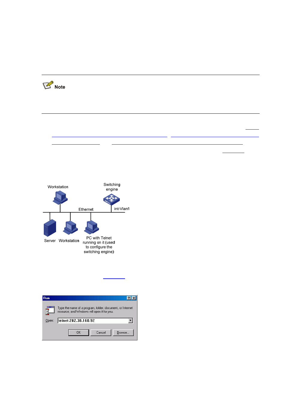
3) Connect your PC/terminal and the switching engine to an Ethernet, as shown in
. Make
sure the port through which the switching engine is connected to the Ethernet belongs to VLAN 1
and the route between your PC and VLAN-interface 1 is reachable.
Figure 4-6
Network diagram for Telnet connection establishment
4) Launch Telnet on your PC, with the IP address of VLAN–interface 1 of the switching engine as the
parameter, as shown in
.
Figure 4-7
Launch Telnet
5) If the password authentication mode is specified, enter the password when the Telnet window
displays “Login authentication” and prompts for login password. The CLI prompt (such as
<System_LSW>) appears if the password is correct. If all VTY user interfaces of the switching