Configuration procedure – H3C Technologies H3C WX3000 Series Unified Switches User Manual
Page 85
11-4
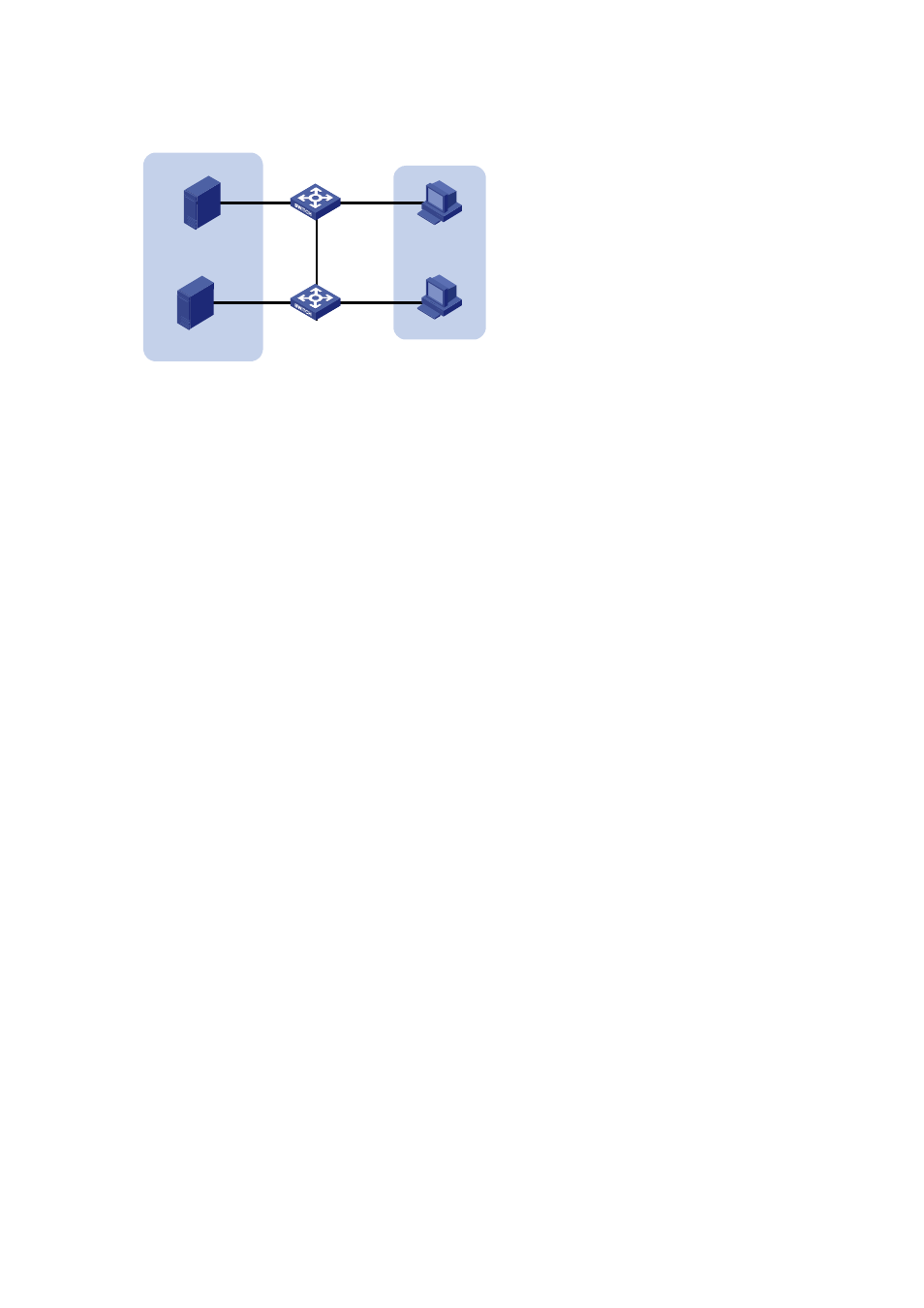
Figure 11-1
Network diagram for VLAN configuration
Switch A
VLAN 101
VLAN 201
Switch B
Server
Server
PC
PC
GEth1/0/1
GEth1/0/2
GEth1/0/10
GEth1/0/3
GEth1/0/12
GEth1/0/11
Configuration procedure
z
Configure Switch A.
# Create VLAN 101, specify its descriptive string as “DMZ”, and add GigabitEthernet 1/0/1 to VLAN 101.
<SwitchA> system-view
[SwitchA] vlan 101
[SwitchA-vlan101] description DMZ
[SwitchA-vlan101] port GigabitEthernet 1/0/1
[SwitchA-vlan101] quit
# Create VLAN 201, and add GigabitEthernet 1/0/2 to VLAN 201.
[SwitchA] vlan 201
[SwitchA-vlan201] port GigabitEthernet 1/0/2
[SwitchA-vlan201] quit
z
Configure Switch B.
# Create VLAN 101, specify its descriptive string as “DMZ”, and add GigabitEthernet 1/0/11 to VLAN
101.
<SwitchB> system-view
[SwitchB] vlan 101
[SwitchB-vlan101] description DMZ
[SwitchB-vlan101] port GigabitEthernet 1/0/11
[SwitchB-vlan101] quit
# Create VLAN 201, and add GigabitEthernet 1/0/12 to VLAN 201.
[SwitchB] vlan 201
[SwitchB-vlan201] port GigabitEthernet 1/0/12
[SwitchB-vlan201] quit
z
Configure the link between Switch A and Switch B.
Because the link between Switch A and Switch B need to transmit data of both VLAN 101 and VLAN
102, you can configure the ports at the end of the link as trunk ports and permit packets of the two
VLANs to pass through.
# Configure GigabitEthernet 1/0/3 of Switch A.
[SwitchA] interface GigabitEthernet 1/0/3
[SwitchA-GigabitEthernet1/0/3] port link-type trunk
[SwitchA-GigabitEthernet1/0/3] port trunk permit vlan 101
[SwitchA-GigabitEthernet1/0/3] port trunk permit vlan 201