Rip configuration example – H3C Technologies H3C WX3000 Series Unified Switches User Manual
Page 660
66-10
RIP Configuration Example
Network requirements
A small-sized company requires that any two nodes in its small office network communicate with each
other, and that the network devices automatically adapt themselves to any topology change so as to
reduce the work of manual maintenance.
In this case, RIP can implement communication between any two nodes.
According to the network requirements, the network topology is designed as shown in
.
Figure 66-1
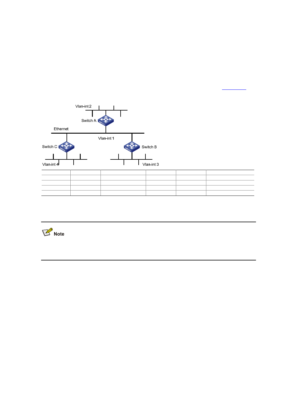
Network diagram for RIP configuration
Device Interface IP
address
Device Interface IP
address
Switch A
Vlan-int1
110.11.2.1/24
Switch B
Vlan-int1
110.11.2.2/24
Vlan-int2 155.10.1.1/24
Vlan-int3 196.38.165.1/24
Switch
C
Vlan-int1
110.11.2.3/24
Vlan-int4
117.102.0.1/16
Configuration procedure
Only the configuration related to RIP is listed below. Before the following configuration, make sure the
Ethernet link layer works normally and the IP addresses of VLAN interfaces are configured correctly.
1) Configure Switch A:
# Configure RIP.
<SwitchA> system-view
[SwitchA] rip
[SwitchA-rip] network 110.11.2.0
[SwitchA-rip] network 155.10.1.0
2) Configure Switch B:
# Configure RIP.
<SwitchB> system-view
[SwitchB] rip
[SwitchB-rip] network 196.38.165.0
[SwitchB-rip] network 110.11.2.0
3) Configure Switch C: