H3C Technologies H3C WX3000 Series Unified Switches User Manual
Page 394
39-12
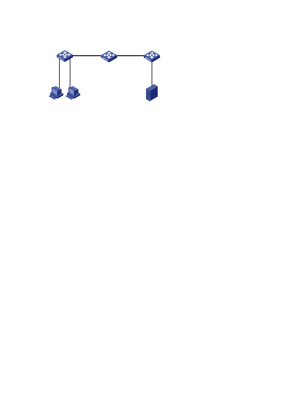
Figure 39-4
Network diagram for remote port mirroring
Switch A
GEth1/0/3
Data detection
device
Dept.1
Dept.2
GEth1/0/1
Switch B
Switch C
GEth1/0 /1
GEth1/0/2
GEth1/0/1
GEth1/0/2
GEth1/0/4
GEth1/0/2
Configuration procedure
1) Configure the source switch (Switch A)
# Create remote source mirroring group 1.
<device> system-view
[device] mirroring-group 1 remote-source
# Configure VLAN 10 as the remote-probe VLAN.
[device] vlan 10
[device-vlan10] remote-probe vlan enable
[device-vlan10] quit
# Configure the source ports, reflector port, and remote-probe VLAN for the remote source mirroring
group.
[device] mirroring-group 1 mirroring-port GigabitEthernet 1/0/1 GigabitEthernet 1/0/2
inbound
[device] mirroring-group 1 reflector-port GigabitEthernet 1/0/4
[device] mirroring-group 1 remote-probe vlan 10
# Configure GigabitEthernet 1/0/3 as trunk port, allowing packets of VLAN 10 to pass.
[device] interface GigabitEthernet 1/0/3
[device-GigabitEthernet1/0/3] port link-type trunk
[device-GigabitEthernet1/0/3] port trunk permit vlan 10
[device-GigabitEthernet1/0/3] quit
# Display configuration information about remote source mirroring group 1.
[device] display mirroring-group 1
mirroring-group 1:
type: remote-source
status: active
mirroring port:
GigabitEthernet1/0/1 inbound
GigabitEthernet1/0/2 inbound
mirroring mac:
mirroring vlan:
reflector port: GigabitEthernet1/0/4
remote-probe vlan: 10
2) Configure the intermediate switch (Switch B)
# Configure VLAN 10 as the remote-probe VLAN.