Assigning video buses to output connectors, Video input/output settings – Roland VR-120HD Direct Streaming AV Mixer User Manual
Page 17
17
Video Input/Output Settings
Assigning Video Buses to Output Connectors
The V-120HD features seven types of video buses. You can assign
the signals from each video output connector/port (HDMI OUT 1–3
connectors, SDI OUT 1–3 connectors, USB STREAM port, DIRECT STREAM
port) and the video shown on this unit’s display to the desired video bus.
Video output connectors and ports
HDMI Out 1–3
HDMI OUT 1–3
connectors
SDI Out 1–3
SDI OUT 1–3
connectors
USB Out
USB STREAM port
Stream/Record
DIRECT STREAM port
LCD Monitor
This unit’s display
Video bus
Explanation
Program
Final output video
Sub Program
Same video as the PROGRAM bus
The SUB PROGRAM bus lets you set whether to
display or hide the PinP & key layers and the DSK
layers, separately from the PROGRAM bus.
You can edit the layer settings to output a different
video from that of the PROGRAM bus.
Preview
Preview output video (the video to be output next)
* The fade-in/out effect (p. 34) is not reflected
here.
AUX
Video of your choice sent to the AUX bus (p. 18)
This lets you allocate a separate output that is
independent of the final output, such as when you
want a specific input video to be a fixed output.
Multi-View
The final output video, preview output video and
the videos allocated to the VIDEO SWITCHER [1]–[8]
buttons (multi-view)
MEMO
You can change the respective videos that are
shown.
Set this by pressing the [MENU] button
Ó
“System”
Ó
“Multi-View Layout” and select “Left”
or “Right”.
Input-View
The input video from the HDMI IN and SDI IN
connectors (shown as 16 separate sections on the
screen)
MEMO
You can change the videos that are shown.
Set this by pressing the [MENU] button
Ó
“System”
Ó
“Input-View Layout”.
Still-View
Still images loaded into the unit (shown as 16
separate sections on the screen)
1 .
With the [INPUT SELECT] button lit up, press the MODE
[SETUP] button.
The setup screen appears.
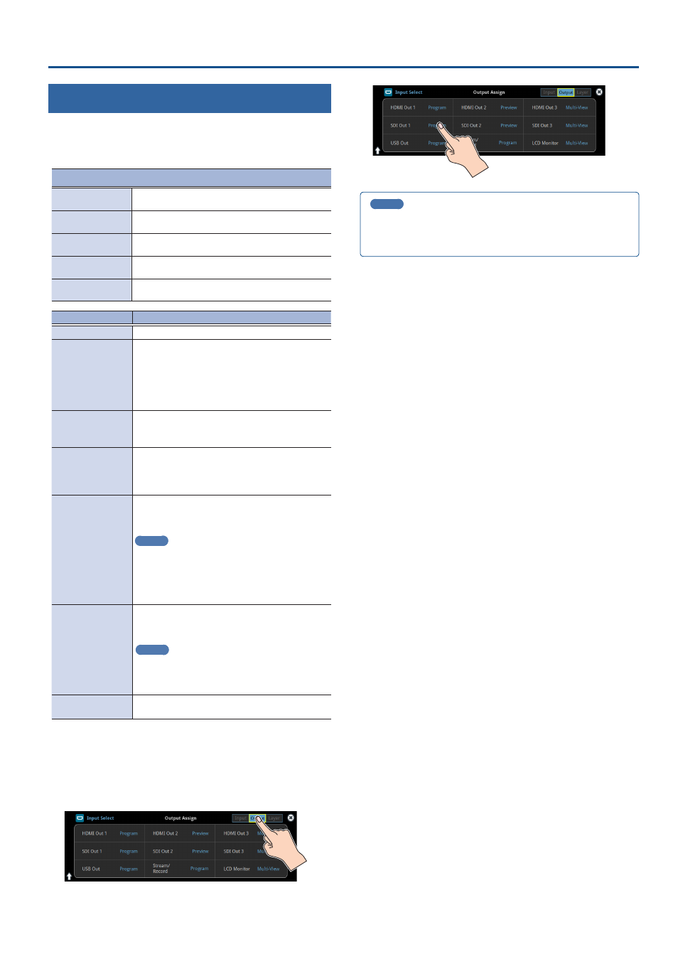
2 .
Touch the page tab at the top right-hand part of the screen
to select page 2 (Output).
The Output Assign screen appears.
3 .
Touch the screen to select the video bus to assign.
MEMO
Assigning the video buses and audio outputs
You can also assign the desired audio buses (Main bus, AUX 1 bus, AUX
2 bus, Monitor bus) for each jack, apart from the video bus (p. 61).