Fluke Biomedical 2MF Index User Manual
Page 115
Appendices
Custom Probe Test Cables and Electrical Simulation Cables
G
G-3
Generic Probe Test Connections
Index 2
Pin
1
1
2
3
4
5
6
7
8
9
10
11
12
13
14
15
SHLD 1
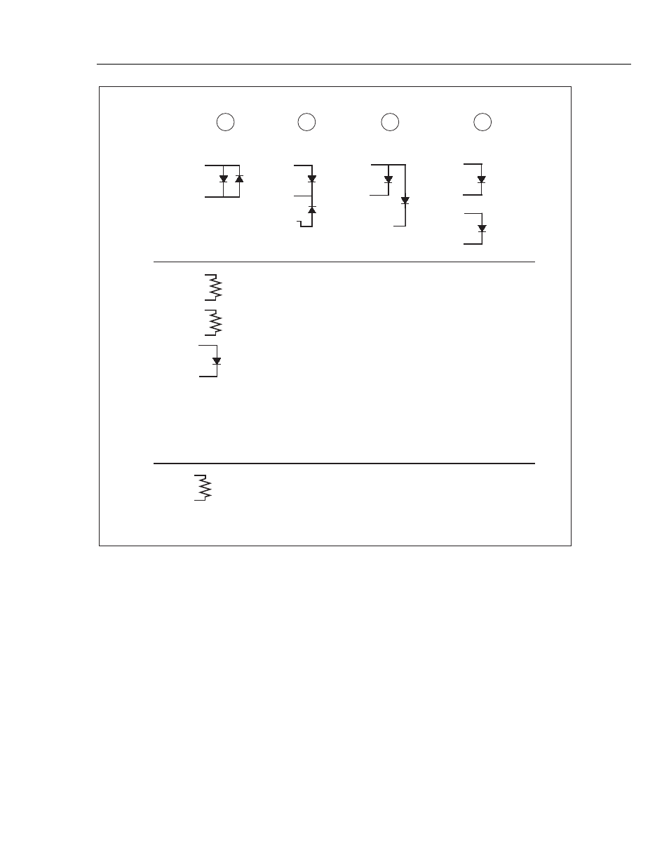
Pins 1 - 4 can be connected 4 ways, identified by the value of the resistor across pins 14 and 15.
R1
10 k
20 k
30 k
40 k
Diode Connection
to Resistor
R
NC
NC
NC
NC
R
R
R
IR
IR
IR
IR
R2
SHLD 2
SHLD 3
NELLCOR
(10 k)
OHMEDA
(30 k)
(20 k)
(40 k)
2
3
4
esl164.eps
Figure G-2. Generic Probe Test Connections
Note
Because of the many different ways probes can be connected, your
Simulator is designed to work with an interface cable that adapts the
Simulator connector to the probe connector.
If you need to test a probe which is not supported by Fluke Biomedical at this time with
an interface cable, the following information will enable you to make your own interface
cable.
Pins 1 through 4 are reserved for LED connections. Figure G-2 shows the four possible
LED arrangements and how to connect each to pins 1 through 4. For example, the typical
Nellcor type probe uses only pins 1 and 2 and has the IR LED anode on pin 1.
How does Index 2MF know which LED arrangement is being used? See pins 14 and 15.
A 1 % resistor is placed across these pins. The value of the resistor versus the LED
arrangement is given in Table G-1.