Photodiode test – Fluke Biomedical 2MF Index User Manual
Page 69
Electrical Probe Test
Probe Test Selection
9
9-3
esl126.eps
The Simulator applies 1.0 mA current AC signal source to the red and infrared LEDs.
The Simulator performs the electrical test separately on each diode to confirm they are
functioning properly. The voltage drop across each element is measured and displayed.
Values can range from 0.0 to 4.0:
•
0.0 Volts = LED shorted
•
1.4 +/- Volts = LED OK
•
Any value of 4.0 or greater will be displayed as “> 4.0.”
esl127.eps
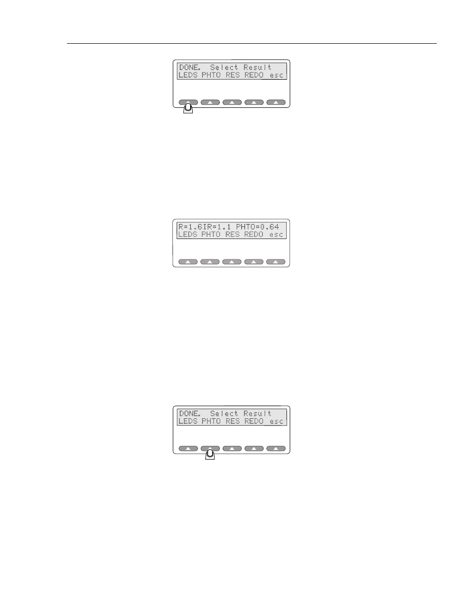
The LEDS test should return a PHTO reading of approximately 0.6 volts if electrically
good. Use the resulting numbers as a baseline for similar probes. For example, 1.6 may
be a typical red LED and 1.1 a typical IR LED result for Nellcor probes. A 0.0 results
would indicate a shorted diode, while >4.0 V would indicate either an open diode or that
the voltage drop across the diodes has exceeded the Simulator’s forward-voltage test
range.
Photodiode Test
This test looks at the probe as a functioning entity. Numbers close to zero support a faulty
probe diagnosis.
Test the photodiode probe by pressing the
PHTO
key.
esl172.eps
The red LED lights up and the Simulator measures the resulting photodiode output. The
red LED then goes out and again measures the output. The difference indicates the
response to a 1 mA LED illuminating current.
The same test measures the infrared LED.
Both tests are repeated multiple times to average out ambient light, with the results
displayed as a pair of numbers; one for red, and one for infrared, on a fixed scale giving
an indication of photodiode response to each color. A higher number yields more
response. Numbers can range from 0-20,000 or more. It is a nominal value only.