Fluke Biomedical 2MF Index User Manual
Page 116
Index 2MF
Users Guide
G-4
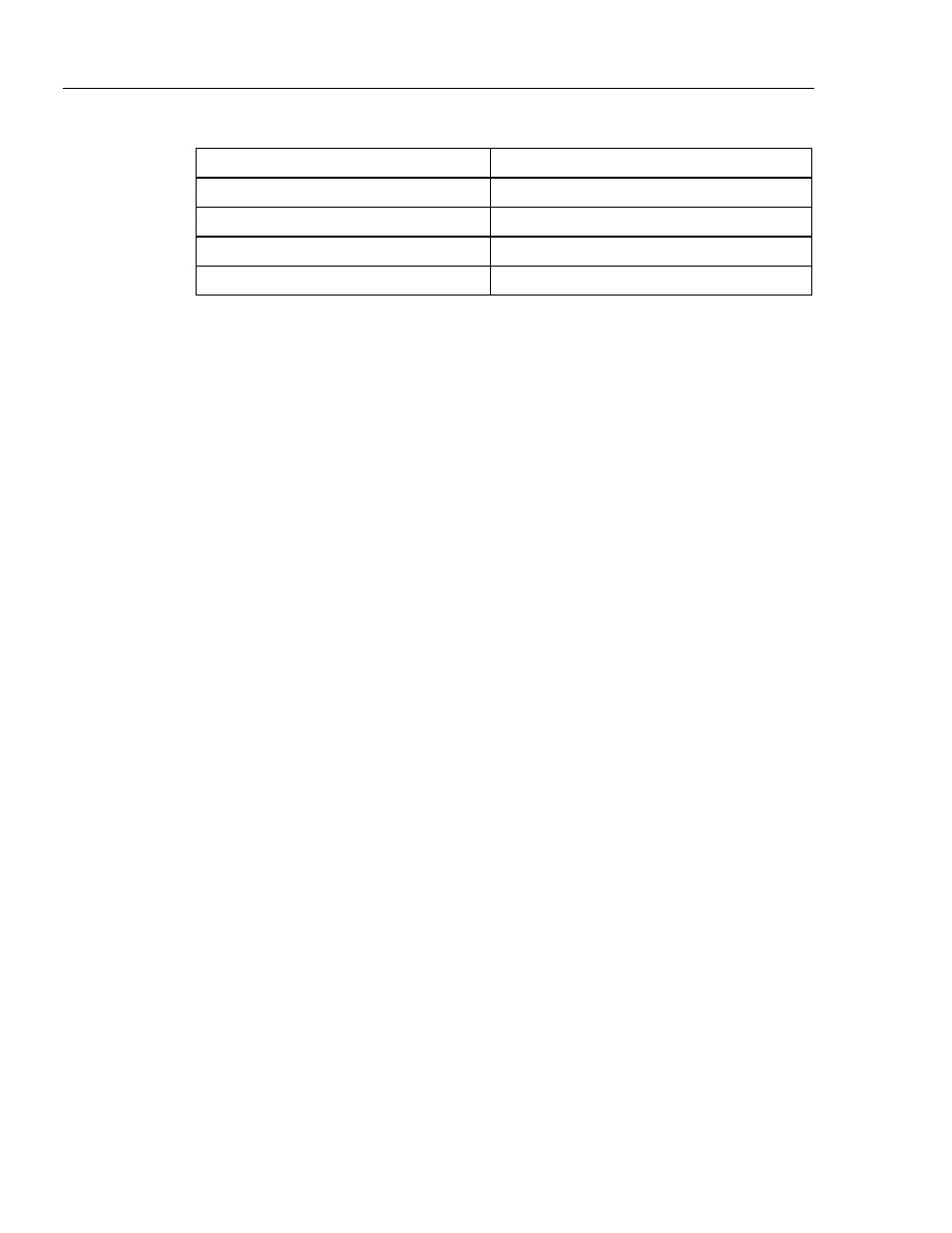
Table G-1. Resistances with LED Arrangements
Technology Options
Typical Oximeter
10 K
Back to back (typical of Nellcor)
20 K
Common cathode
30 K
Common Anode (typical of Ohmeda)
40 K
Completely separate
Before testing the probe, the Simulator reads this resistor to determine the LED
connection being tested.
Examining the 15-pin connector further:
1. Up to two LED calibration resistors can be tested by the Simulator. Connect them as
R1 and R2 in Figure G-1.
2. The probe photodiode is to be connected to pins 9 and 10 as shown.
3. Finally, up to three shields can be tested for shorts to other leads. These would be
connected to any of pins 11, 12, or 13.
Refer to Figure G-3, an example of the Ohmeda probe test connections.