Resistance testing – Fluke Biomedical 2MF Index User Manual
Page 70
Index 2MF
Users Guide
9-4
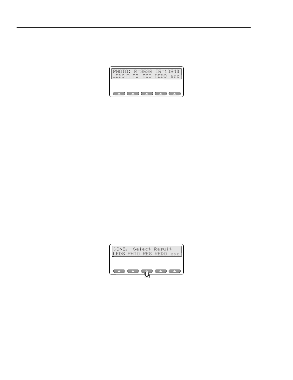
Develop baseline values for comparison purposes when testing marginal, defective, or
suspect probes by logging voltage readings from operational probes.
These values update continually during testing.
esl128.eps
Note
During the photodiode test, the finger probe being tested should not be
attached to the Index 2MF finger.
Displayed numbers will vary due to both the general probe condition and
as a function of the distance and angle between the two LEDs and the photo
detector.
Take care to maintain alignment when inspecting the SpO2 sensor.
Reusable SpO2 sensors with built-in spring clips typically maintain
consistent alignment between the LEDs and the photo detector, therefore
yielding consistent results.
However, test results when inspecting a flexible disposable “tape style”
probe will fluctuate unless you take care to maintain the optimal
mechanical position of the probe. As a suggestion, wrap the disposable
probe on a small white plastic cylinder or tube (not your finger) to maintain
the mechanical alignment of the LEDs to the photo detector.
These values update continually.
Resistance Testing
Press
RES
key
at the "DONE. SELECT RESULT" screen.
esl173.eps
The Simulator checks for resistances between all wires (separately testing each one,
every pin to every other pin, except for those wire pair combinations where a LED would
draw normal current).
The Simulator displays resistances under 150,000 Ohms.
Pressing the
MORE
softkey displays all pin combinations that have resistances. Results
must be interpreted in context of the probe schematic; some probes contain resistors,
some do not. A resistance where none should exist indicates a faulty probe. For example,
a resistance between a resistor shown on the probe schematic as floating and one of the
LED or photodiode leads would certainly be faulty.