Fluke Biomedical 2MF Index User Manual
Page 119
Appendices
Custom Probe Test Cables and Electrical Simulation Cables
G
G-7
1
2
3
4
GENERIC OXIMETER PINS BY USAGE
INDEX 2
PIN
CONNECTION FOR FLOATING SILICON DIODE:
TRUE DIFFERENTIAL SOURCE
SINGLE-ENDED POSITIVE OR NEGATIVE
CURRENT OR VOLTAGE PHOTO DIODE
SIMULATION SOURCES
OXIMETER SHIELD PINS TO BE USED AS NORMAL, BUT NOT TIED TO ANYTHING AT INDEX.
GROUND
A:
POSITIVE VOTAGE PULSES
B:
NEGATIVE VOLTAGE PULSES
C,D:
VOLTAGE TO CURRENT SOURCE CONVERSION
RESISTORS. PUT IN CABLE FOR SPECIFIC
OXIMETERS A/R.
NELLCOR
IR
IR
IR
IR
R
R
R
R
OHMEDA
1
2
3
4
5
6
7
8
9
esl162.eps
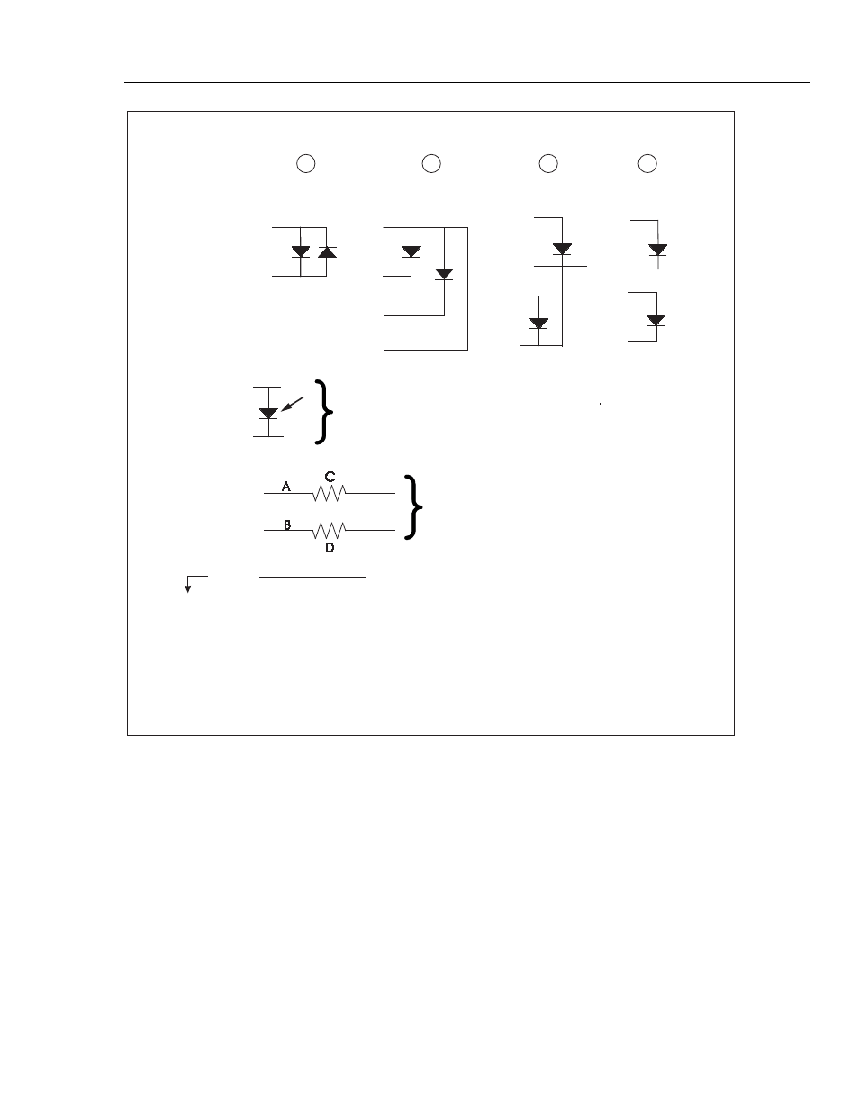
Figure G-4. Generic Pins by Usage
Pins 1 through 4 show the different ways oximeter probes can have their LEDs
connected. For example, if the Simulator were used to simulate an Ohmeda probe, the
Ohmeda drive pins would be connected to the Simulator connector on pins 1 through 4 as
shown. Current scaling resistors may be required (see Figure G-5, the actual Ohmeda
interface cable).
An oximeter expects to see light flashes detected by a floating silicon photodiode. Pins 5
and 6 of the Simulator provide a floating silicon photodiode, which is driven with the
simulated signal. It must be connected to the correct polarity inputs of the oximeter.
Scaling resistors on its output may be required (see Figure G-5, the actual Ohmeda
interface cable).