NavCom StarUtil Rev.G User Manual
Page 34
StarUtil User Guide – Rev. G
4-32
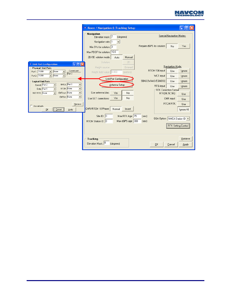
Figure 20: Rover / Navigation & Tracking Setup Window
Click this button to configure the physical and logical unit
window opens (see Figure 20). Refer to the section
, for more information.
is button to set the appropriate bias adjustment values for the
ptional). The Vertical Antenna Bias window opens (see Figure 21):
• Phase Center Adjustment (H1): The offset in millimeters from the physical center of the
antenna (the element) to the Mechanical Reference Plane (MRP). The MRP is at the
bottom of the BSW antenna mount. The range limits are -128 to 127mm.
• Radius of Antenna Body (R): The measurement in millimeters from the physical center of
the antenna to the edge of the antenna. For a pole, enter 0. For a tripod, the range limits
are -32768 to 32767mm.
•
Body: For a pole, the vertical measurement in millimeters from
the Mechani
d, the
measureme
l point. The range
nna’s provides the appropriate
9
Unit Port Configuration Button:
ports. The Unit Port Configuration
above, Configure Unit Ports
9
Antenna Setup Button: Click th
antenna model in use (o
Slant Range of Antenna
cal Reference Plane (MRP) to the control point. For a tripo
nt in millimeters from the edge of the antenna to the contro
limits are -32768 to 32767mm.
A label on the bottom of NavCom supplied ante
measurements for the antenna in use.