Rtcm configuration, Base rtcm port configuration, Figure 53: 5d – rtg rtk offset vector – NavCom StarUtil Rev.G User Manual
Page 59: Figure 54: rtcm port configuration
StarUtil User Guide – Rev. G
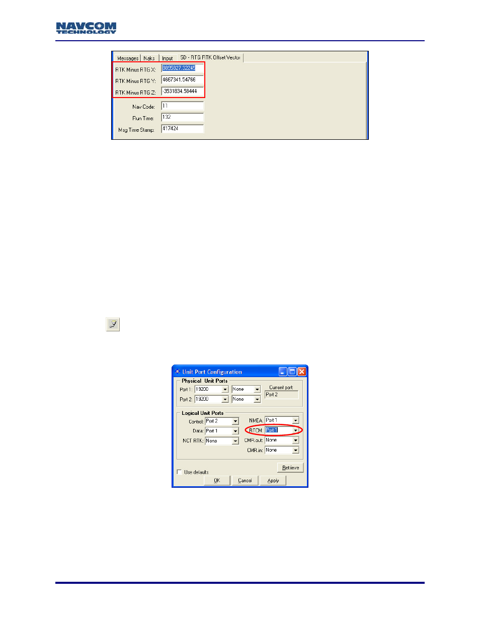
Figure 53: 5D – RTG RTK Offset Vector
Refer to Figure 53 for the steps below:
34. For
1
RTK Extend™ users only, select View > 5D – RTG RTK Offset Vector.
35. Verify that the RTG RTK offset vector is received from the base station.
RTCM Configuration
Except for the steps in this section, RTCM configuration is the same as NCT RTK configuration.
Perform the steps below to configure a base station to transmit and a rover to receive RTCM
corrections. Perform the additional steps in the section above, NCT RTK Configuration, to
complete the configuration.
Base RTCM Port Configuration
efer to Figure 54 for the steps below:
1. Click
the
R
icon on the toolbar to set the communications between the radio modem and
the GPS receiver. The
To open the
Setup > Ports.
Unit Port Configuration window opens.
window from the menu bar, select Receiver >
Figure 54: RTCM Port Configuration
Set the baud rate, as appropriate, for Port 1 (19200 default). Do not change the default
parity (None).
. Set
the
RTCM logical port to Port 1 (equivalent to Com1).
Models RT-3010 & RT-3020 only (internal radio): Set RTCM logical port to Port Radio.
2.
3
1
Separate Software Option Required
5-57