Cmr configuration, Base cmr.out port configuration, Base cmr configuration – NavCom StarUtil Rev.G User Manual
Page 65: Figure 60: cmr.out port configuration
StarUtil User Guide – Rev. G
CMR Configuration
Except for the steps in this section, CMR configuration is the same as NCT RTK configuration.
Perform the steps below to configure a base station to transmit and a rover to receive CMR or
CMR+ corrections. Perform the additional steps in the section above, NC
T RTK Configuration,
plete the configuration.
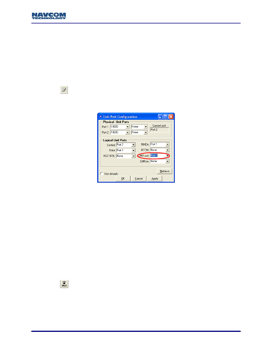
Refer to Figure 60 for the steps below:
1. Click
the
to com
Base CMR.out Port Configuration
icon on the to
een the radio modem and
the GPS receiver. The
To open the
Setup > Ports.
olbar to set the communication betw
Unit Port Configuration window opens.
window from the menu bar, select Receiver >
Figure 60: CMR.out Port Configuration
ot change the default
or
10 & RT-3020 only (with internal radio): Set the CMR.out logical
en click the Retrieve button to confirm that the receiver accepts
Figure 61 for the steps below:
. Click
the
2. Set the baud rate, as appropriate, for Port 1 (19200 default). Do n
parity (None).
3. Set
the
CMR.out logical port to Port 1 (equivalent to Com1). This setting is for CMR
CMR+ corrections.
Models RT-30
port to Port Radio.
4. Click
the
Apply button and th
the settings.
5. Click
the
OK button to exit the window.
Base CMR Configuration
Refer to
icon on the toolbar to configure the base station to transmit CMR corrections.
The Base Configuration window opens.
To open the window from the menu bar, select Receiver > Setup > Base.
6
5-63