Mstp configuration example, Network requirements, Network diagram – H3C Technologies H3C S3100 Series Switches User Manual
Page 266: Configuration procedure
1-47
To do...
Use the command...
Remarks
Display information about the root
port of the instance where the switch
reside
display stp root
Clear statistics about MSTP
reset stp
[ interface interface-list ]
Available in user view
MSTP Configuration Example
Network requirements
Implement MSTP in the network shown in
to enable packets of different VLANs to be
forwarded along different MSTIs. The detailed configurations are as follows:
z
All switches in the network belong to the same MST region.
z
Packets of VLAN 10, VLAN 30, VLAN 40, and VLAN 20 are forwarded along MSTI 1, MSTI 3, MSTI
4, and MSTI 0 respectively.
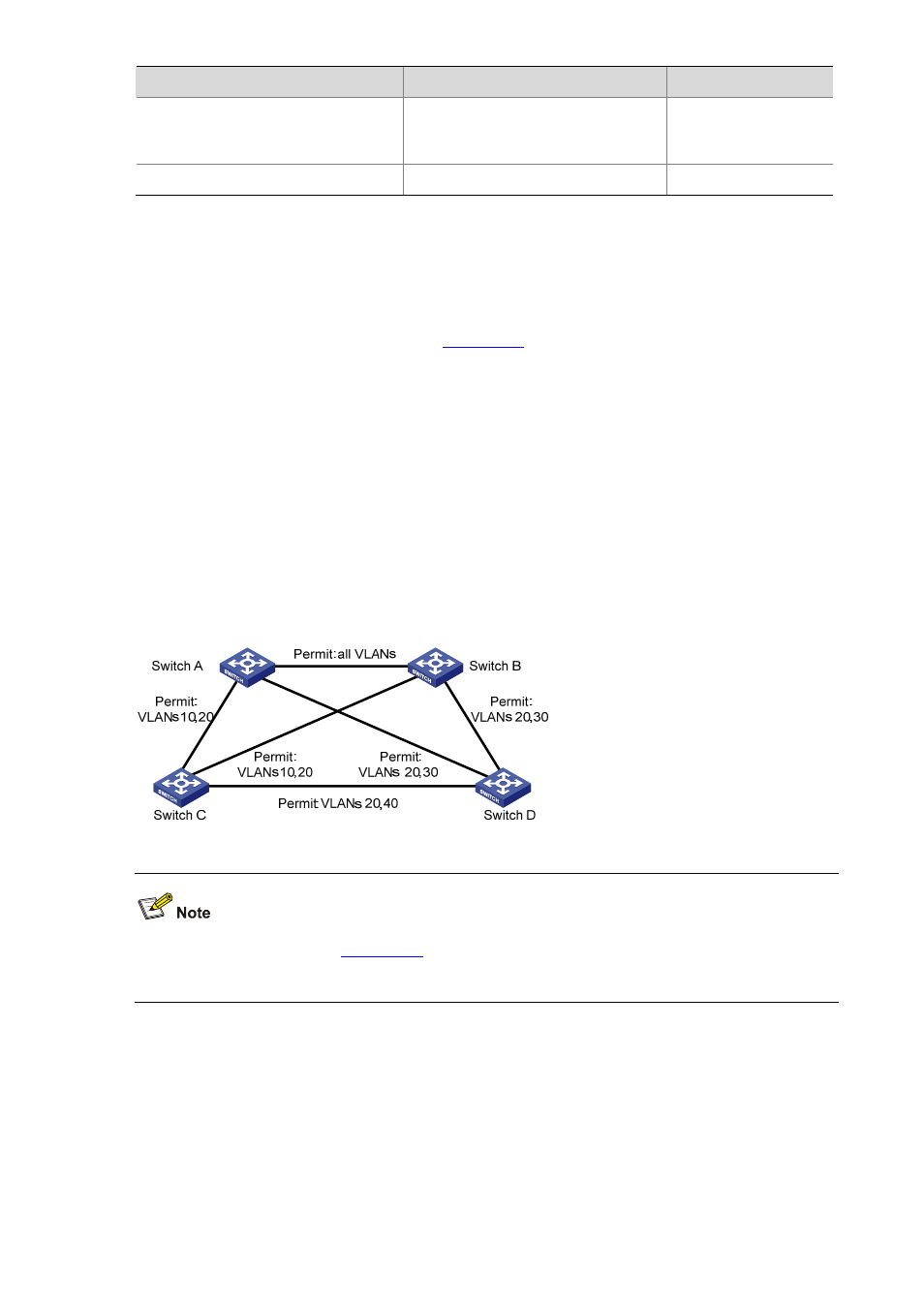
In this network, Switch A and Switch B operate on the convergence layer; Switch C and Switch D
operate on the access layer. VLAN 10 and VLAN 30 are limited in the convergence layer and VLAN 40
is limited in the access layer. Switch A and Switch B are configured as the root bridges of MSTI 1 and
MSTI 3 respectively. Switch C is configured as the root bridge of MSTI 4.
Network diagram
Figure 1-10
Network diagram for MSTP configuration
The word “permit” shown in
means the corresponding link permits packets of specific
VLANs.
Configuration procedure
1) Configure Switch A
# Enter MST region view.
<Sysname> system-view
[Sysname] stp region-configuration
# Configure the region name, VLAN-to-instance mapping table, and revision level for the MST region.