Stack configuration example, Network requirements, Network diagram – H3C Technologies H3C S3100 Series Switches User Manual
Page 634: Configuration procedure
1-5
Operation
Command
Description
Display the stack status
information on a slave switch
display stacking
The display command can be
executed in any view.
The displayed information
indicates that the local switch is
a slave switch. The information
such as stack number of the
local switch, and the MAC
address of the main switch in
the stack is also displayed.
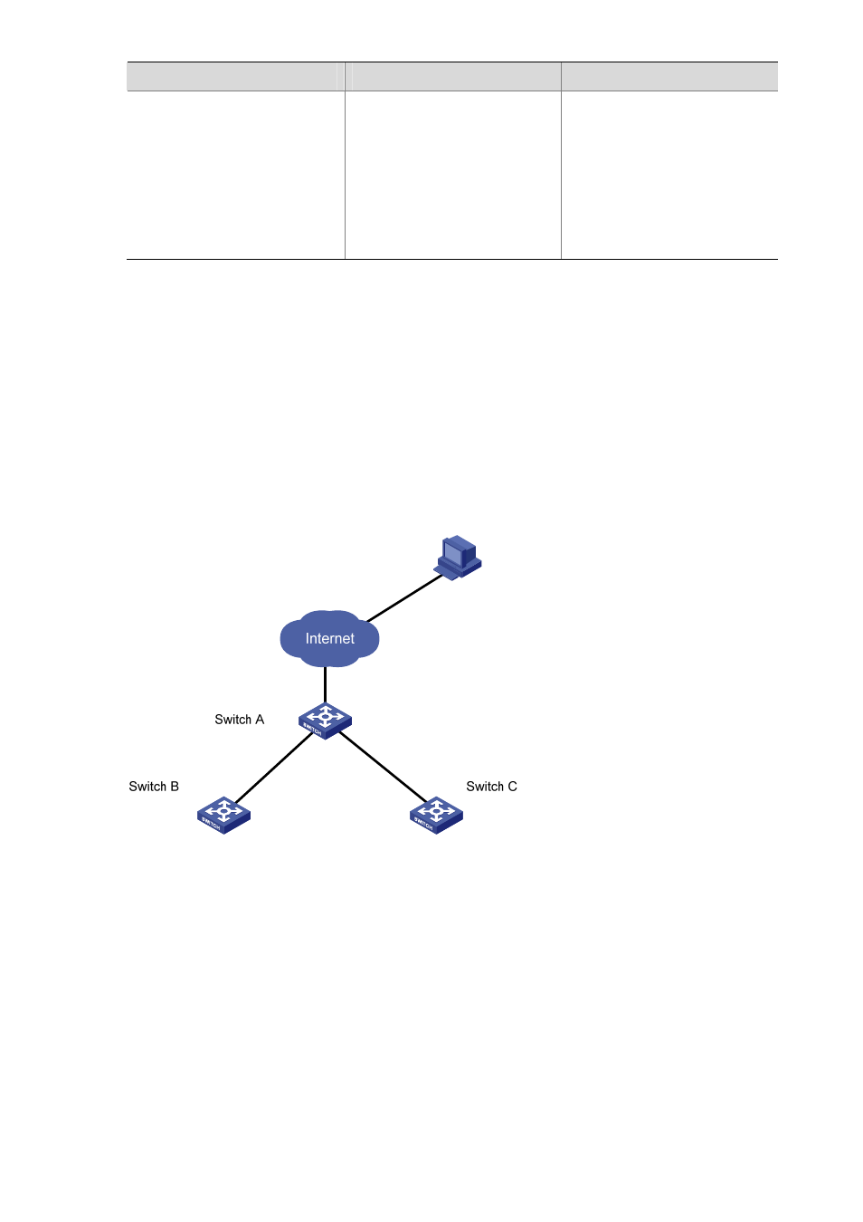
Stack Configuration Example
Network requirements
z
Connect Switch A, Switch B and Switch C with each other through their stack ports to form a stack,
in which Switch A acts as the main switch, while Switch B and Switch C act as slave switches.
z
Configure Switches B and Switch C through Switch A.
Network diagram
Figure 1-1 Network diagram for stack configuration
Configuration procedure
# Configure the IP address pool for the stack on Switch A.
<Sysname> system-view
[Sysname] stacking ip-pool 129.10.1.15 3
# Create the stack on switch A.
[Sysname] stacking enable
[stack_0.Sysname] quit
<stack_0.Sysname>
# Display the information about the stack on switch A.
<stack_0.Sysname> display stacking