Network diagram, Configuration procedure – H3C Technologies H3C S3100 Series Switches User Manual
Page 855
3-5
z
Enable the service provider network to transmit STP packets of the customer network through
BPDU tunnel. The destination MAC address for tunnel packets is 010f-e233-8b22.
z
Enable the VLAN-VPN feature for the service provider network, and enable the service provider
network to use VLAN 100 to transmit data packets of the customer network.
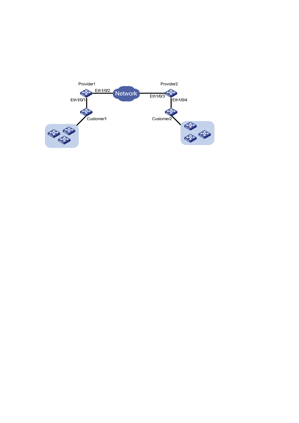
Network diagram
Figure 3-4 Network diagram for BPDU Tunnel configuration
Configuration procedure
1) Configure
Provide1.
# Disable STP on Ethernet1/0/1.
<Sysname> system-view
[Sysname] interface Ethernet 1/0/1
[Sysname-Ethernet1/0/1] stp disable
# Enable the BPDU tunnel feature for STP BPDUs on Ethernet1/0/1.
[Sysname-Ethernet1/0/1] bpdu-tunnel stp
# Enable the VLAN-VPN feature on Ethernet1/0/1 and use VLAN 100 to transmit user data packets
through BPDU tunnels.
[Sysname-Ethernet1/0/1] port access vlan 100
[Sysname-Ethernet1/0/1] vlan-vpn enable
# Configure the destination MAC address for protocol packets transmitted through the BPDU tunnel.
[Sysname-Ethernet1/0/1] quit
[Sysname] bpdu-tunnel tunnel-dmac 010f-e233-8b22
# Configure Ethernet1/0/2 as a trunk port that permits packets of all VLANs.
[Sysname] interface Ethernet 1/0/2
[Sysname-Ethernet1/0/2] port link-type trunk
[Sysname-Ethernet1/0/2] port trunk permit vlan all
2) Configure
Provider2.
# Disable STP on Ethernet1/0/4.
<Sysname> system-view
[Sysname] interface Ethernet 1/0/4
[Sysname-Ethernet1/0/4] stp disable
# Enable BPDU tunnel for STP packets.