Network diagram, Configuration procedure – H3C Technologies H3C S3100 Series Switches User Manual
Page 673
2-3
Ethernet 1/0/1 through Ethernet 1/0/10 of Switch A are used by users of group A, who have the following
requirements:
z
The PoE function can be enabled on all ports in use.
z
Signal mode is used to supply power.
z
The PoE priority for Ethernet 1/0/1 through Ethernet 1/0/5 is Critical, whereas the PoE priority for
Ethernet 1/0/6 through Ethernet 1/0/10 is High.
z
The maximum power for Ethernet 1/0/1 through Ethernet 1/0/5 ports is 3,000 mW, whereas the
maximum power for Ethernet 1/0/6 through Ethernet 1/0/10 is 15,400 mW.
Based on the above requirements, two PoE profiles are made for users of group A.
z
Apply PoE profile 1 for Ethernet 1/0/1 through Ethernet 1/0/5;
z
Apply PoE profile 2 for Ethernet 1/0/6 through Ethernet 1/0/10.
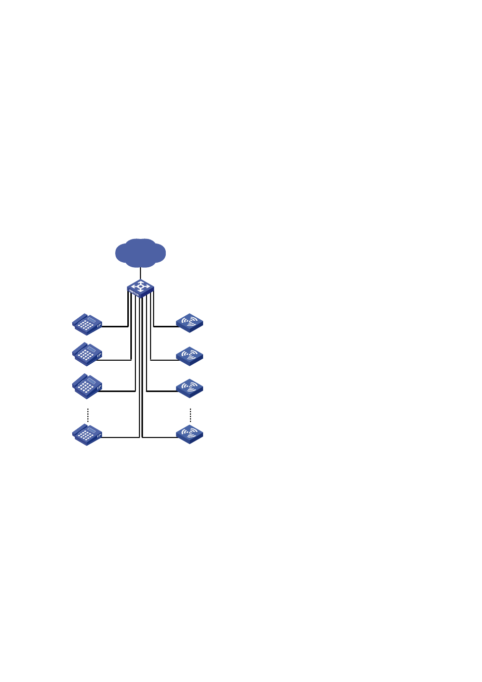
Network diagram
Figure 2-1
PoE profile application
Network
IP Phone
Switch A
AP
IP Phone
IP Phone
IP Phone
AP
AP
AP
Eth1/0/1~Eth1/0/5
Eth1/0/6~Eth1/0/10
Configuration procedure
# Create Profile1, and enter PoE profile view.
<SwitchA> system-view
[SwitchA] poe-profile Profile1
# In Profile1, add the PoE policy configuration applicable to Ethernet 1/0/1 through Ethernet 1/0/5 ports
for users of group A.
[SwitchA-poe-profile-Profile1] poe enable
[SwitchA-poe-profile-Profile1] poe mode signal
[SwitchA-poe-profile-Profile1] poe priority critical
[SwitchA-poe-profile-Profile1] poe max-power 3000
[SwitchA-poe-profile-Profile1] quit
# Display detailed configuration information for Profile1.