Network requirements, Network diagram, Configuration procedure – H3C Technologies H3C S3100 Series Switches User Manual
Page 750
1-37
Click Browse… to bring up the file selection window, navigate to the private key file and click OK.
5) From the window shown in
, click Open. If the connection is normal, you will be
prompted to enter the username.
When Switch Acts as Client for Password Authentication
Network requirements
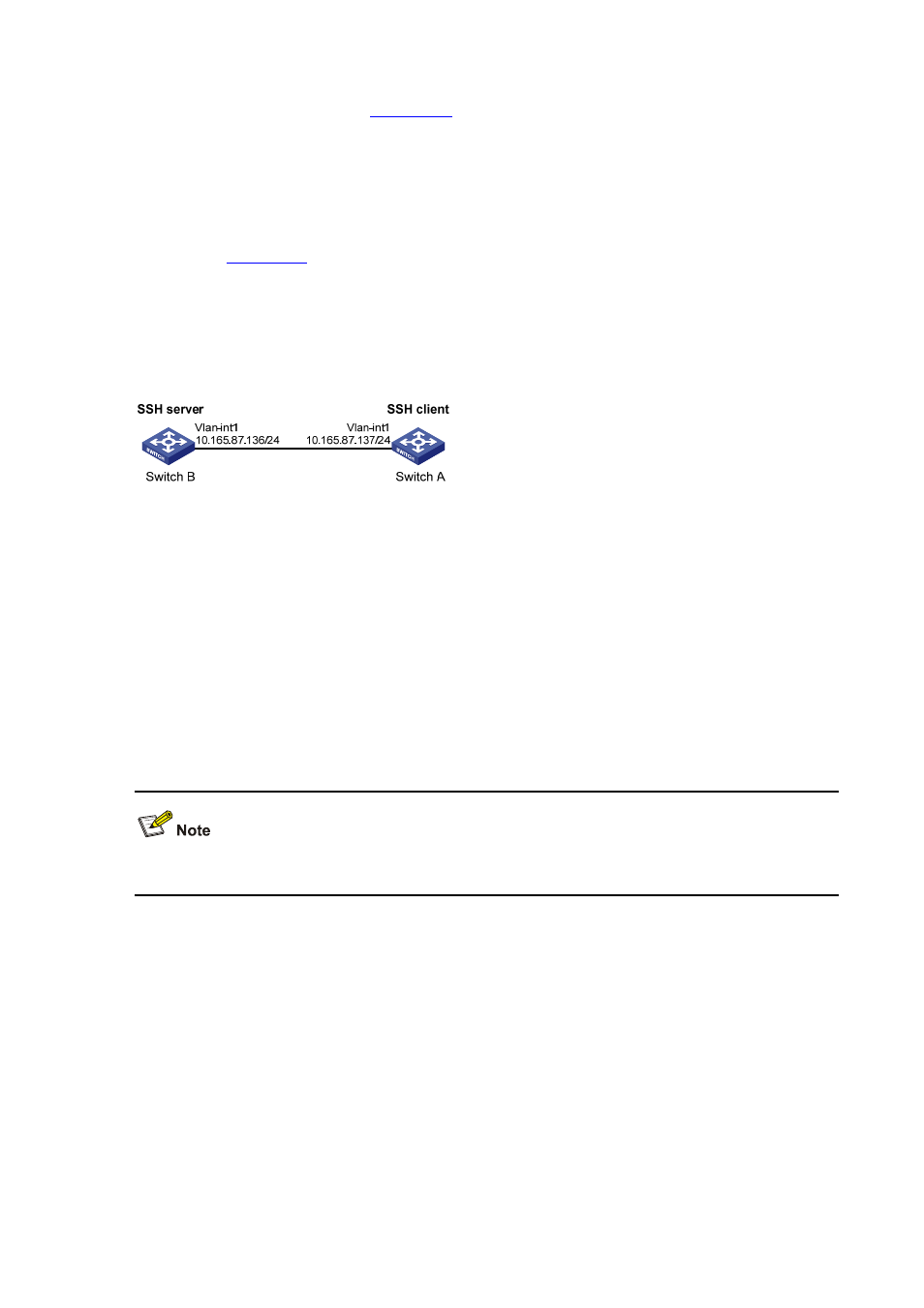
As shown in
, establish an SSH connection between Switch A (SSH Client) and Switch B
(SSH Server) for secure data exchange. The user name for login is client001 and the SSH server’s IP
address is 10.165.87.136. Password authentication is required.
Network diagram
Figure 1-29 Switch acts as client for password authentication
Configuration procedure
z
Configure Switch B
# Create a VLAN interface on the switch and assign an IP address, which the SSH client will use as the
destination for SSH connection.
<SwitchB> system-view
[SwitchB] interface vlan-interface 1
[SwitchB-Vlan-interface1] ip address 10.165.87.136 255.255.255.0
[SwitchB-Vlan-interface1] quit
Generating the RSA and DSA key pairs on the server is prerequisite to SSH login.
# Generate RSA and DSA key pairs.
[SwitchB] public-key local create rsa
[SwitchB] public-key local create dsa
# Set the authentication mode for the user interfaces to AAA.
[SwitchB] user-interface vty 0 4
[SwitchB-ui-vty0-4] authentication-mode scheme
# Enable the user interfaces to support SSH.
[SwitchB-ui-vty0-4] protocol inbound ssh
[SwitchB-ui-vty0-4] quit
# Create local user client001, and set the authentication password to abc, the login protocol to SSH,
and user command privilege level to 3.