Ip filtering configuration example, Network requirements, Network diagram – H3C Technologies H3C S3100 Series Switches User Manual
Page 547: Configuration procedure
3-15
[Sysname-Ethernet1/0/2] quit
# Enable unauthorized DHCP server detection on Ethernet 1/0/3.
[Sysname] interface ethernet1/0/3
[Sysname-Ethernet1/0/3] dhcp-snooping server-guard enable
# Specify the method for handling unauthorized DHCP servers as shutdown on Ethernet 1/0/3..
[Sysname-Ethernet1/0/3] dhcp-snooping server-guard method shutdown
IP Filtering Configuration Example
Network requirements
As shown in
, Ethernet1/0/1 of the S3100-EI switch is connected to DHCP server and
Ethernet1/0/2 is connected to Host A. The IP address and MAC address of Host A are 1.1.1.1 and
0001-0001-0001 respectively. Ethernet1/0/3 and Ethernet1/0/4 is connected to DHCP Client B and
Client C.
z
Enable DHCP snooping on the switch, and specify Ethernet1/0/1 as the DHCP snooping trusted
port.
z
Enable IP filtering on Ethernet1/0/2, Ethernet1/0/3, and Ethernet1/0/4 to prevent attacks to the
server from clients using fake source IP addresses.
z
Create static binding entries on the switch, so that Host A using a fixed IP address can access the
external network.
Network diagram
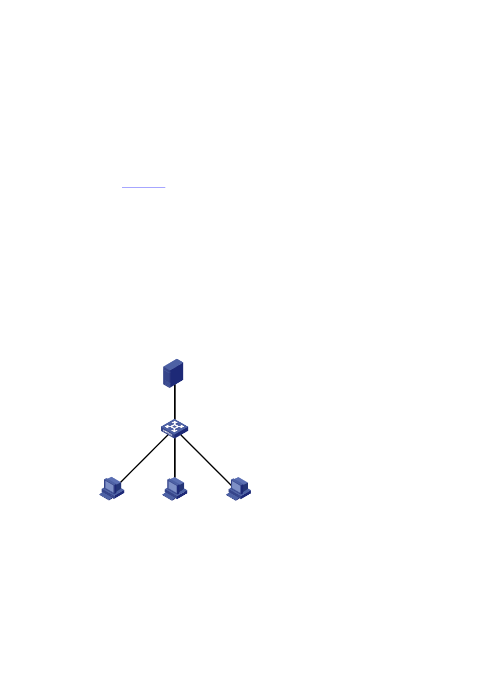
Figure 3-10 Network diagram for IP filtering configuration
Switch
DHCP Snooping
Eth1/0/2
Client C
Eth1/0/1
DHCP Server
Client B
Host A
IP:1.1.1.1
MAC:0001-0001-0001
Eth1/0/3
Eth1/0/4
Configuration procedure
# Enable DHCP snooping on the switch.
<Switch> system-view
[Switch] dhcp-snooping
# Specify Ethernet1/0/1 as the trusted port.
[Switch] interface Ethernet1/0/1