Igmp snooping configuration examples, Configuring igmp snooping, Network requirements – H3C Technologies H3C S3100 Series Switches User Manual
Page 303: Network diagram, Configuration procedure
2-16
Table 2-20 Display and maintain IGMP Snooping
Operation
Command
Remarks
Display the current IGMP
Snooping configuration
display igmp-snooping
configuration
Display IGMP Snooping message
statistics
display igmp-snooping
statistics
Display the information about IP
and MAC multicast groups in one
or all VLANs
display igmp-snooping group
[ vlan vlanid ]
You can execute the display
commands in any view.
Clear IGMP Snooping statistics
reset igmp-snooping statistics
You can execute the reset
command in user view.
IGMP Snooping Configuration Examples
Configuring IGMP Snooping
Network requirements
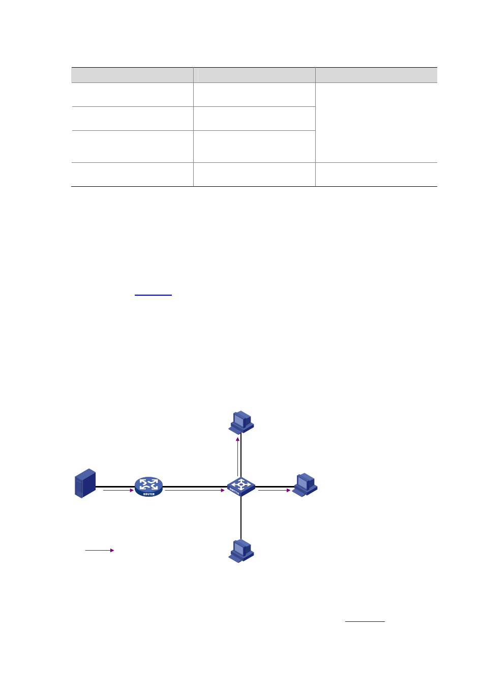
To prevent multicast traffic from being flooded at Layer 2, enable IGMP snooping on Layer 2 switches.
z
As shown in
, Router A connects to a multicast source (Source) through Ethernet1/0/2,
and to Switch A through Ethernet1/0/1.
z
Run PIM-DM and IGMP on Router A. Run IGMP snooping on Switch A. Router A acts as the IGMP
querier.
z
The multicast source sends multicast data to the multicast group 224.1.1.1. Host A and Host B are
receivers of the multicast group 224.1.1.1.
Network diagram
Figure 2-3 Network diagram for IGMP Snooping configuration
Multicast packets
Source
Router A
Switch A
Receiver
Receiver
Host B
Host A
Host C
1.1.1.1/24
Eth1/0/4
Eth1/0/2
Eth1/0/3
IGMP querier
Eth1/0/1
Eth1/0/1
10.1.1.1/24
Eth1/0/2
1.1.1.2/24
VLAN100
Configuration procedure
1) Configure the IP address of each interface
Configure an IP address and subnet mask for each interface as per
. The detailed
configuration steps are omitted.