Interface cable, Connecting the interface cable – H3C Technologies H3C MSR 50 User Manual
Page 115
3-11
The following table describes the LEDs on the MIM-1FE/MIM-2FE/MIM-4FE panel:
Table 3-11 Description of the LEDs on the MIM-1FE/MIM-2FE/MIM-4FE panel
LED
Description
LINK
z
OFF means the Ethernet link is not connected.
z
ON means the link is connected.
ACTIVE
z
OFF means no data is being transmitted or received;
z
Blinking means data is being received or/and transmitted.
Interface cable
1) Ethernet
cable
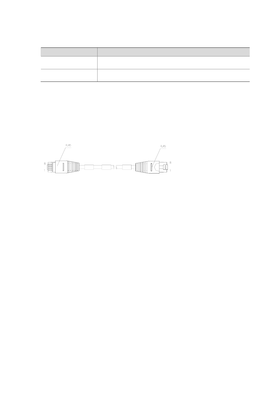
Ethernet cables for FE modules are category 5 twisted pair cables with RJ-45 connectors (see the
figure below). Pins 1 and 2 of the interface are for data transmission, and Pins 3 and 6 are for data
receiving.
Figure 3-12 Ethernet cable
2) Making Ethernet cable
Category 5 twisted pairs are adopted for making Ethernet cables. Each category 5 twisted pair is
composed of 8 cores that are identified and grouped by color of insulation sheath. Usually a solid color
wire and the white/solid color wire for it are in pairs. Sometimes, however, wires are also paired by color
dots.
Ethernet cables fall into two categories: straight-through cables and crossover cables:
z
Straight-through cable: The sequences of the twisted pairs crimped by RJ-45 connectors at both
ends are the same. It is used for the connection between a terminal device (e.g., PC and router)
and a Hub/LAN Switch. The cables delivered with the Router are straight-through cables.
z
Crossover cable: The sequences of the twisted pairs crimped by RJ-45 connectors at both ends
are different. It is used for the connection between terminal devices (e.g., PC and router) .And it
can be made by the user.
For the pinouts of straight-through Ethernet cable and crossover Ethernet cable, see Low-End and
Mid-Range Series Routers Cable Manual.
Connecting the interface cable
Step1 (Use a crossover cable for the connection to a PC/router and straight-through cable to a Hub/LAN
Switch.) Plug one end of the cable to an Ethernet port of the router and another end to the desired peer
device;
Step2 Check the status of LINK LED on the FE module panel: ON means the link is connected and OFF
means the link is not connected. In the latter case, check the line.