Connecting the interface cable, Fic-8t1/fic-8t1-f, Introduction – H3C Technologies H3C MSR 50 User Manual
Page 238
4-43
:
Both T1 cable and network interface connector are optional accessories. Order them together with
FIC-1T1/FIC-2T1/FIC-4T1 and FIC-1T1-F/FIC-2T1-F/FIC-4T1-F. By default, they are not provided.
Connecting the interface cable
z
Before you connect a port, read its label carefully. A wrong connection can cause damages to the
interface module and even the device.
z
If outdoor cabling is involved, consider to install a special lightning arrester at the input end of the
T1 interface cable for better lightning protection.
Step1 Insert one end of the T1 cable into the to-be-connected RJ-45 connector on the module.
Step2 Connect the other end of the cable to another device directly if the cable is long enough. If not, extend
the cable before you do that, as shown in the following figure:
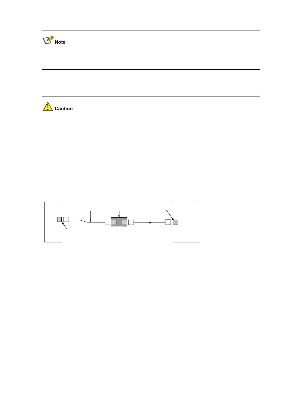
Figure 4-55 Extending a T1 cable
Router
DDN, etc
Network interface connector
Straight-through cable
-
Router
DDN, etc
Network interface connector
-
Router
DDN, etc
Network interface connector
-
Router
DDN, etc
RJ-45
Network interface connector
-
RJ-45
Router
DDN, etc
Network interface connector
-
Router
DDN, etc
Network interface connector
-
Router
DDN, etc
Network interface connector
Router
DDN, etc
RJ-45
Network interface connector RJ-45
shielding network cable)
T1 cable (100-ohm straight-through
Router
DDN, etc
Network interface connector
Straight-through cable
-
Router
DDN, etc
Network interface connector
-
Router
DDN, etc
Network interface connector
-
Router
DDN, etc
RJ-45
Network interface connector
-
RJ-45
Router
DDN, etc
Network interface connector
-
Router
DDN, etc
Network interface connector
-
Router
DDN, etc
Network interface connector
Router
DDN, etc
RJ-45
Network interface connector RJ-45
shielding network cable)
T1 cable (100-ohm straight-through
Step3 Power on the router, and check the behavior of the LINK LED on the module panel: OFF means fault
occurs on the line. Check the line status.
FIC-8T1/FIC-8T1-F
Introduction
1) FIC-8T1
FIC-8T1, the 8-port channelized T1/PRI interface module, transmits, receives, and processes eight
channels of T1 data traffic. In addition, you can use the module for other purposes, such as CT1 access
and the ISDN PRI function.
2) FIC-8T1-F
FIC-8T1-F, the 8-port fractional T1 interface module, is different from the FIC-8T1 module in the sense
that: