Interface leds, Interface optical fiber – H3C Technologies H3C MSR 50 User Manual
Page 219
4-24
Attribute
FIC-1CPOS(E)/FIC-1CPOS(T)
Type
Multi-mode
short-haul
Single mode
medium-haul
Single mode
long-haul
Single mode
ultra-long-haul
Min.
–19.0 dBm
–15.0 dBm
–5.0 dBm
–5.0 dBm
Optical
transmitt
er power
Max.
–14.0 dBm
–8.0 dBm
0. dBm
0. dBm
Receiver sensitivity
–30.0 dBm
–28.0 dBm
–34.0 dBm
–34.0 dBm
Overload optical
power
–14.0 dBm
–7.0 dBm
–9.0 dBm
–10.0 dBm
Central wavelength
1310 nm
1310 nm
1310 nm
1550 nm
Fiber type
62.5/125
μm
multi-mode
9/125 μm single
mode
9/125 μm single
mode
9/125 μm single
mode
Max. transmission
segment
2 km (1.2 mi.)
15 km (9.3 mi.)
40 km (24.9 mi)
80 km (49.7 mi)
For a long-haul fiber-optic interface, the transmission distance must be longer than 25 km (15.53 miles)
to allow the receiver to work. In case of closer distances, insert an optical attenuator to reduce the input
optical power.
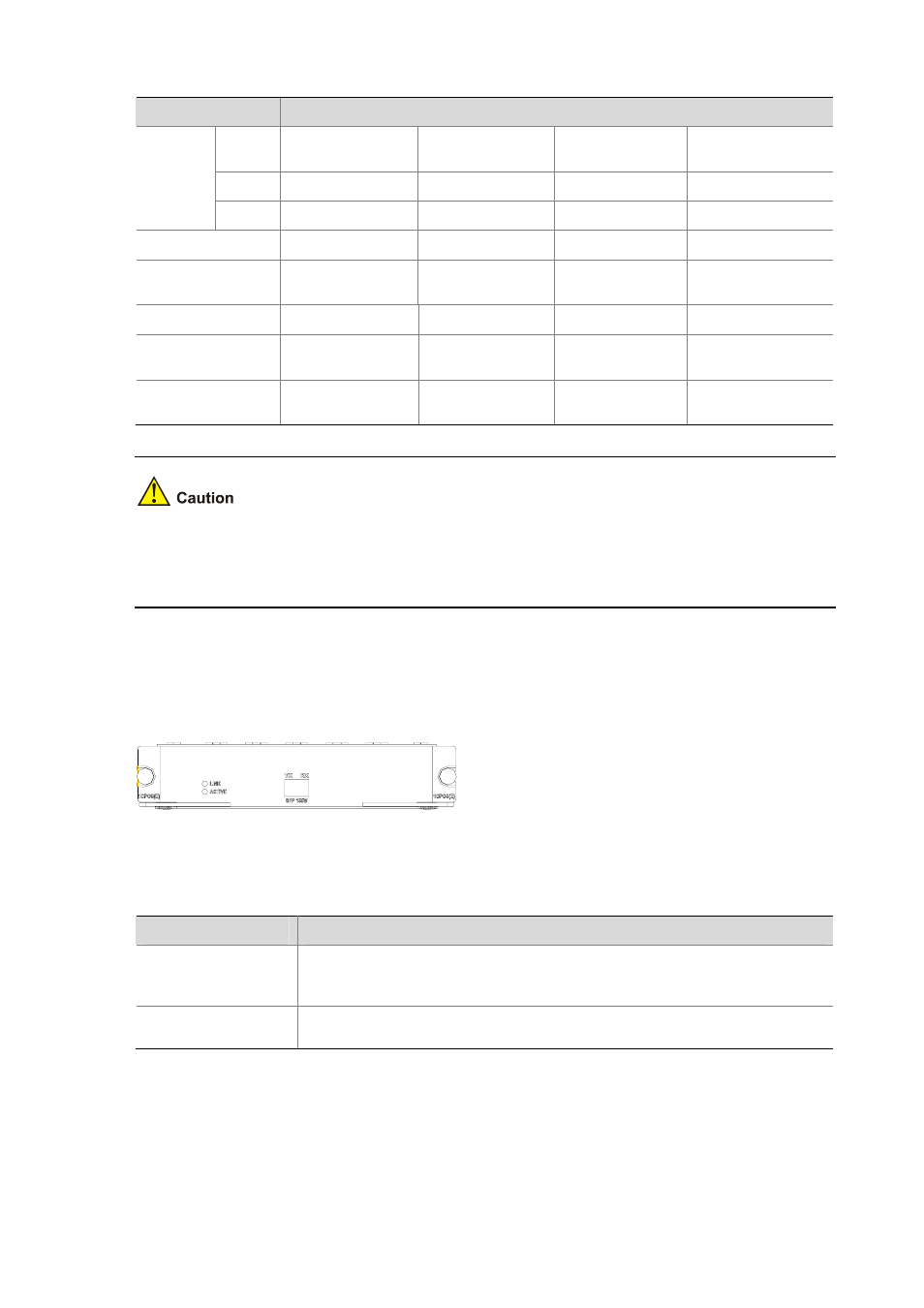
Interface LEDs
The following figure illustrates the FIC-1CPOS panel:
Figure 4-26 FIC-1CPOS panel
The following table describes the LEDs on the FIC-1CPOS panel.
Table 4-24 LEDs on the FIC-1CPOS panel
LED
Description
LINK/ACT
z
OFF means no link is present;
z
ON means a link is present.
z
Blinking means data is being received or transmitted.
LP/AL
z
ON means a loopback interface is configured.
z
Blinking means an alarm is present on the physical link.
Interface optical fiber
The FIC-1CPOS can only be connected to an optical fiber cable with an LC-type fiber-optic connector.