Interface cable, Connecting the interface cable – H3C Technologies H3C MSR 50 User Manual
Page 262
4-67
Figure 4-86 FIC-1E1POS panel
Table 4-55 LEDs on the FIC-1E1POS panel
LED
Description
LINK/ACT
z
ON means a carrier signal is detected.
z
Blinking means data is being received or transmitted.
z
OFF means no carrier signals are detected.
LP/AL
z
ON means the interface is in loopback.
z
Blinking means an AIS, LFA, or RAI alarm signal is present.
z
OFF means no loopback or alarm is present.
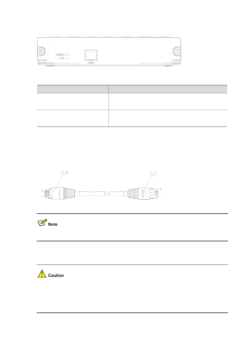
Interface cable
The interface cable of the FIC-1E1POS is a 120-ohm shielding E1 cable, using RJ-45 connectors on
the two ends. The following figure illustrates this type of cable.
Figure 4-87 The FIC-1E1POS interface cable
This cable is optional, so you need to order one separately.
Connecting the interface cable
z
If outdoor cabling is involved, consider to install a special lightning arrester at the input end of the
interface cable for better lightning protection.
z
Before connecting a port, read its label carefully. A wrong connection may cause damages to the
interface module and even the device.
If the FIC has been properly installed, follow these steps to connect the cable: