Connecting the interface optical fiber, Interface mode switchover – H3C Technologies H3C MSR 50 User Manual
Page 220
4-25
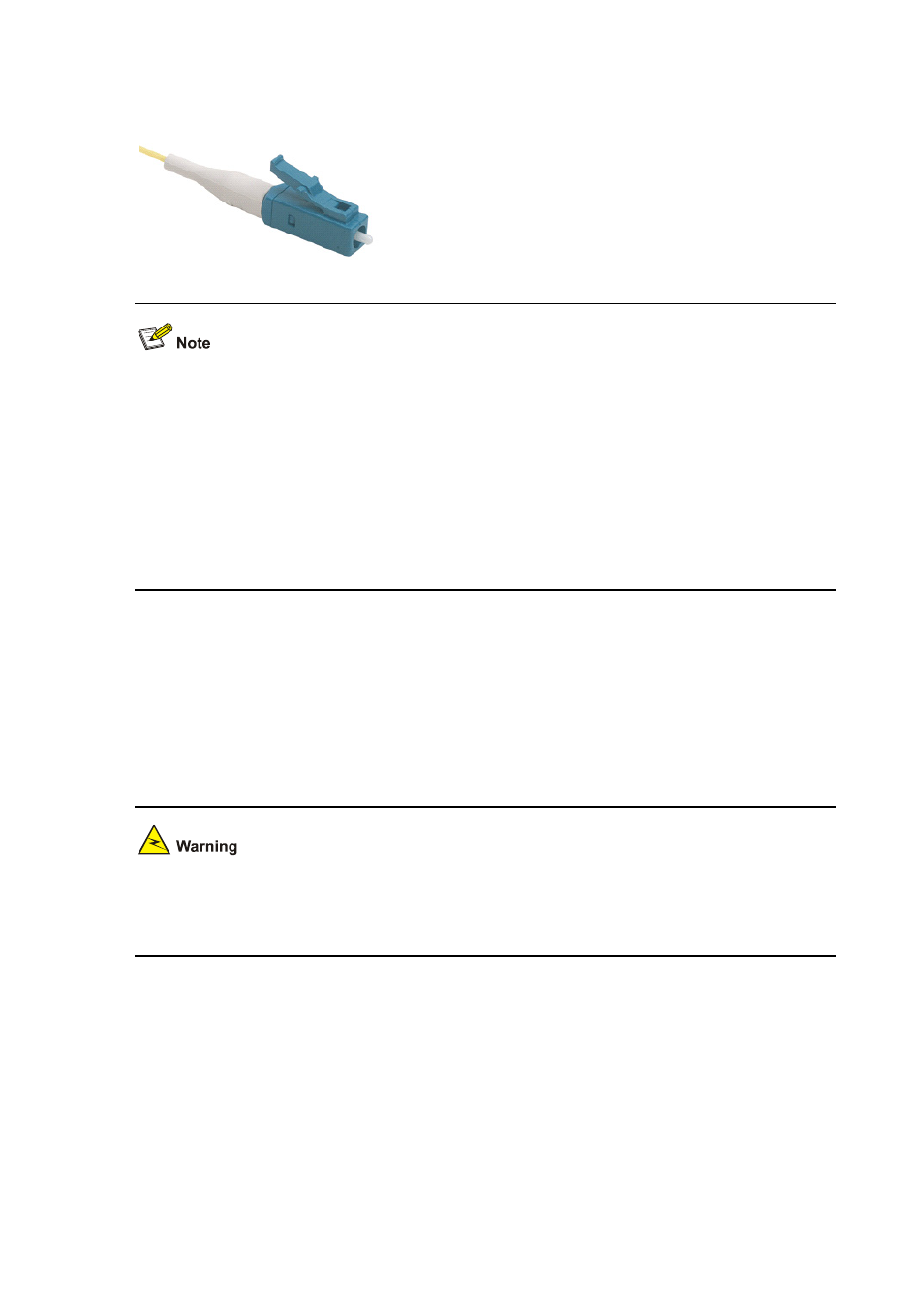
Figure 4-27 LC-type fiber-optic connector
Fiber-optic connectors, according to ITU, are passive components used to stably but not permanently
connect two or more optical fibers. They are indispensable to a fiber-optic communications system in
the sense that it allows add/drop connections between optical channels.
Many types of fiber-optic connectors are available, such as:
z
FC: Round fiber-optic connector with screw thread
z
ST: Round plug-in fiber-optic connector
z
LC: Square fiber-optic connector
z
MT-RJ: Square fiber-optic transceiver connector
Connecting the interface optical fiber
Step1 Insert the SFP module into its corresponding slot.
Step2 Locate the Rx and Tx fiber-optic interfaces on the interface module. Use two fibers to connect the
FIC-CPOS to another device: Rx to Tx and Tx to Rx.
Step3 Power on the device and read the state of the LINK/ACT LED for the FIC-1CPOS interface: ON
means the Rx link is present and OFF means the opposite. In the latter case, check the line status.
Because invisible laser radiation may be emitted from the aperture of an optical port when no fiber is
connected or the dust cap is removed, do not stare into the open aperture. Cover the dust cap when no
fiber is connected to the optical port.
Interface mode switchover
You can switch the FIC-1CPOS to operate in E1 and T1 interface modes at the command line interface
(CLI). Perform the following:
1) Insert the FIC-1CPOS into the FIC slot of the router and then power on the router.
2) Use
the
cadr-mode command in system view to set the interface mode. The following shows the
FIC-1CPOS module is inserted in slot 4 of the device.
# Enter system view
<Sysname> system-view