Interface leds, Interface cable – H3C Technologies H3C MSR 50 User Manual
Page 273
4-78
Interface LEDs
The following figure illustrates the FIC-2BSV panel.
Figure 4-99 FIC-2BSV panel
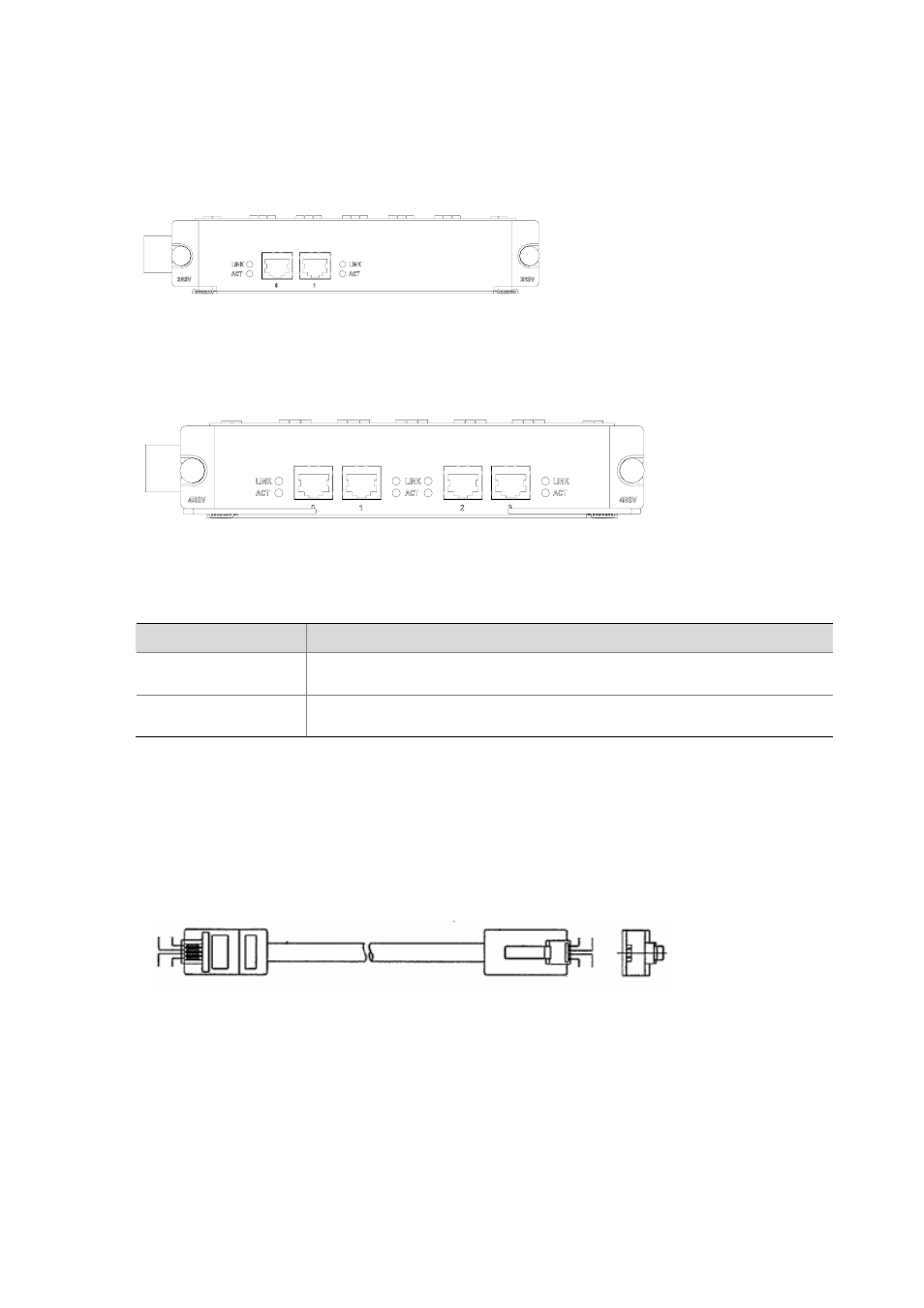
The following figure illustrates the FIC-4BSV panel.
Figure 4-100 FIC-4BSV panel
The following table describes the LEDs on the FIC-2BSV/FIC-4BSV panel.
Table 4-64 LEDs on the FIC-2BSV/FIC-4BSV panel
LED
Description
LINK
z
OFF means no link is present;
z
ON means a link is present.
ACT
z
OFF means no data is being transmitted or received;
z
Blinking means data is being transmitted or received.
Interface cable
When a BSV interface works in user mode, it uses a straight-through ISDN S/T interface cable for
connection. At the two ends of the cable are RJ-45 connectors with pins 3 and 6 for data transmission
and pins 4 and 5 for data receiving.
Figure 4-101 Straight-through ISDN S/T cable
GreenYellow
RedBlack
Yellow
Green
Black
Red
GreenYellow
RedBlack
Yellow
Green
Black
Red
GreenYellow
RedBlack
Yellow
Green
Black
Red
GreenYellow
RedBlack
Yellow
Green
Black
Red
When a BSV interface works in network mode, it uses a crossover ISDN S/T interface cable for
connection, with pins 3 and 6 for data transmission and pins 4 and 5 for data receiving. At one end of
the cable is an RJ-45 male connector for connecting the FIC-2BSV/FIC-4BSV interface and at the other
end of the cable is an RJ-45 female connector for connecting a TE device.