Interface leds – H3C Technologies H3C MSR 50 User Manual
Page 127
3-23
Table 3-22 Interface attributes of the MIM-IMA-4E1/ MIM-IMA-8E1
Description
Attribute
MIM-IMA-4E1
(75-ohm)
MIM-IMA-8E1
(75-ohm)
MIM-IMA-4E1
(120-ohm)
MIM-IMA-8E1
(120-ohm)
Connector DB68
Number of
connectors
1
Interface standard ITU-G.703, ITU-G.704
Interface rate
2.048 Mbps
Cable type
75-ohm 4E1
conversion cable
75-ohm 8E1
conversion cable
120-ohm 4E1
conversion cable
120-ohm 8E1
conversion cable
Max transmission
distance
500 m (1640.4 ft.)
150 m (492.1 ft.)
Operating mode
ATM E1 independent link/IMA bundle mode
Supported service AAL5 (ATM adaptation layer 5)
Protocol
PPPoA, PPPoEoA, IPoA, IPoEoA
Service type
CBR/VBR-rt/VBR-nrt/UBR
Interface LEDs
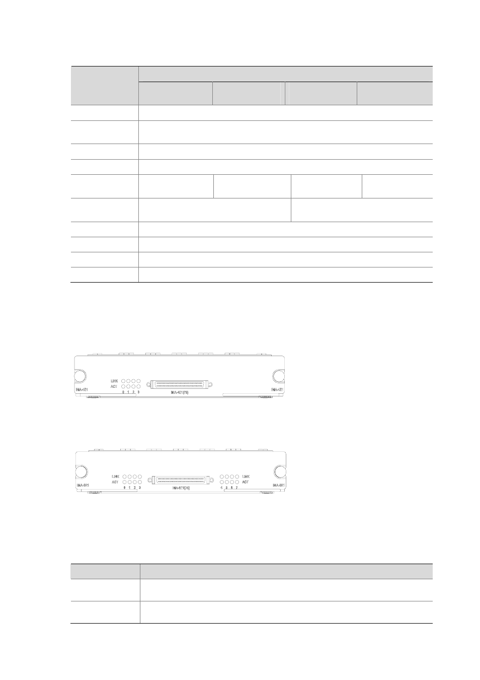
The following figures illustrate the MIM-IMA-4E1 and MIM-IMA-8E1 panels.
Figure 3-23 MIM-IMA-4E1 (75-ohm) panel
Figure 3-24 MIM-IMA-8E1 (75-ohm) panel
The LEDs on the MIM-IMA-4E1 panel have the same functionality as those on the MIM-IMA-8E1 panel.
The following table describes these LEDs.
Table 3-23 Description of the LEDs on the IMA-4E1/IMA-8E1 panel
LED
Description
LINK
z
OFF means no link is present;
z
ON means a link is present.
ACT
z
OFF means no data is being transmitted or received.
z
ON means data is being transmitted or received.