Interface leds, Table 4-46 set the jumpers on the fic-4bse – H3C Technologies H3C MSR 50 User Manual
Page 249
4-54
Table 4-46 Set the jumpers on the FIC-4BSE
Jumper settings & description
Default
S2
z
To use a 100-ohm matched resistance for data transmission,
place the jumper over pins 1 and 2.
z
To do otherwise, place the jumper over jump pins 2 and 3.
z
See
Interface 0
S1
z
To use a 100-ohm matched resistance for data receiving, place
the jumper over jump pins 1 and 2.
z
To do otherwise, place the jumper over jump pins 2 and 3.
z
See
S4
z
To use a 100-ohm matched resistance for data transmission,
place the jumper over pins 1 and 2.
z
To do otherwise, place the jumper over jump pins 2 and 3.
z
See
Interface 1
S3
z
To use a 100-ohm matched resistance for data receiving, place
the jumper over jump pins 1 and 2.
z
To do otherwise, place the jumper over jump pins 2 and 3.
z
See
S6
z
To use a 100-ohm matched resistance for data transmission,
place the jumper over pins 1 and 2.
z
To do otherwise, place the jumper over jump pins 2 and 3.
z
See
Interface 2
S5
z
To use a 100-ohm matched resistance for data receiving, place
the jumper over jump pins 1 and 2.
z
To do otherwise, place the jumper over jump pins 2 and 3.
z
See
S8
z
To use a 100-ohm matched resistance for data transmission,
place the jumper over pins 1 and 2.
z
To do otherwise, place the jumper over jump pins 2 and 3.
z
See
Interface 3
S7
z
To use a 100-ohm matched resistance for data receiving, place
the jumper over jump pins 1 and 2.
z
To do otherwise, place the jumper over jump pins 2 and 3.
z
See
The jumpers are
placed over
jump pins 2 and
3, meaning
100-ohm
matched
resistances are
not used.
Interface LEDs
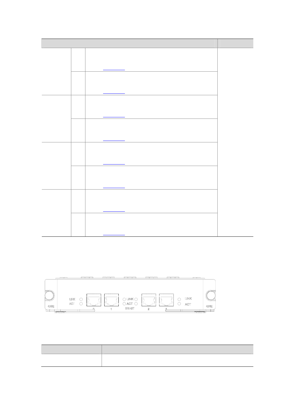
The following figure illustrates the FIC-4BSE panel.
Figure 4-66 FIC-4BSE panel
The following table describes the LEDs on the module panel.
Table 4-47 LEDs on the FIC-4BSE panel
LED
Description
LINK
z
OFF means no link is present.
z
ON means a link is present.