Interface cable, Connecting the interface cable – H3C Technologies H3C MSR 50 User Manual
Page 242
4-47
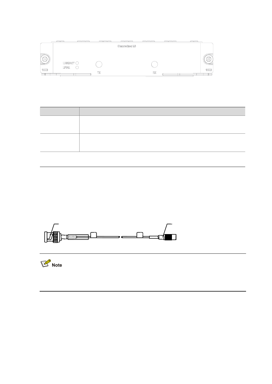
Figure 4-58 FIC-1CE3 panel
The following table describes the LEDs on the module panel.
Table 4-38 LEDs on the FIC-1CE3 panel
LED
Description
LINK/ACT
z
ON means the carrier signal has been received.
z
OFF means no carrier signal has been received.
z
Blinking means data is being transmitted or/and received.
LP/AL
z
ON means the interface is in a loopback.
z
Blinking means an AIS, LFA, or RAI alarm signal is present.
z
OFF means no loopback or alarm is present.
Note:
AIS = Alarm indication signal; LFA = loss of frame alignment; RAI = Remote alarm indication
Interface cable
The external interface provided by the FIC-1CE3 uses two SMB sockets respectively for data
transmitting (Tx) and data receiving (Rx). The interface transmits in 75-ohm unbalanced mode and
uses a pair of 75-ohm unbalanced coaxial cables to connect another device.
Figure 4-59 E3/T3 cable
BNC connector
SMB connector
BNC connector
SMB connector
BNC connector
SMB connector
BNC connector
SMB connector
BNC connector
SMB connector
z
The FIC-1CE3 and the FIC-1CT3 use the same cable, called E3/T3 cable in this manual.
z
The standard equipping package of the FIC-1CE3 does not include the interface cable.
Connecting the interface cable