Interface cable – H3C Technologies H3C MSR 50 User Manual
Page 137
3-33
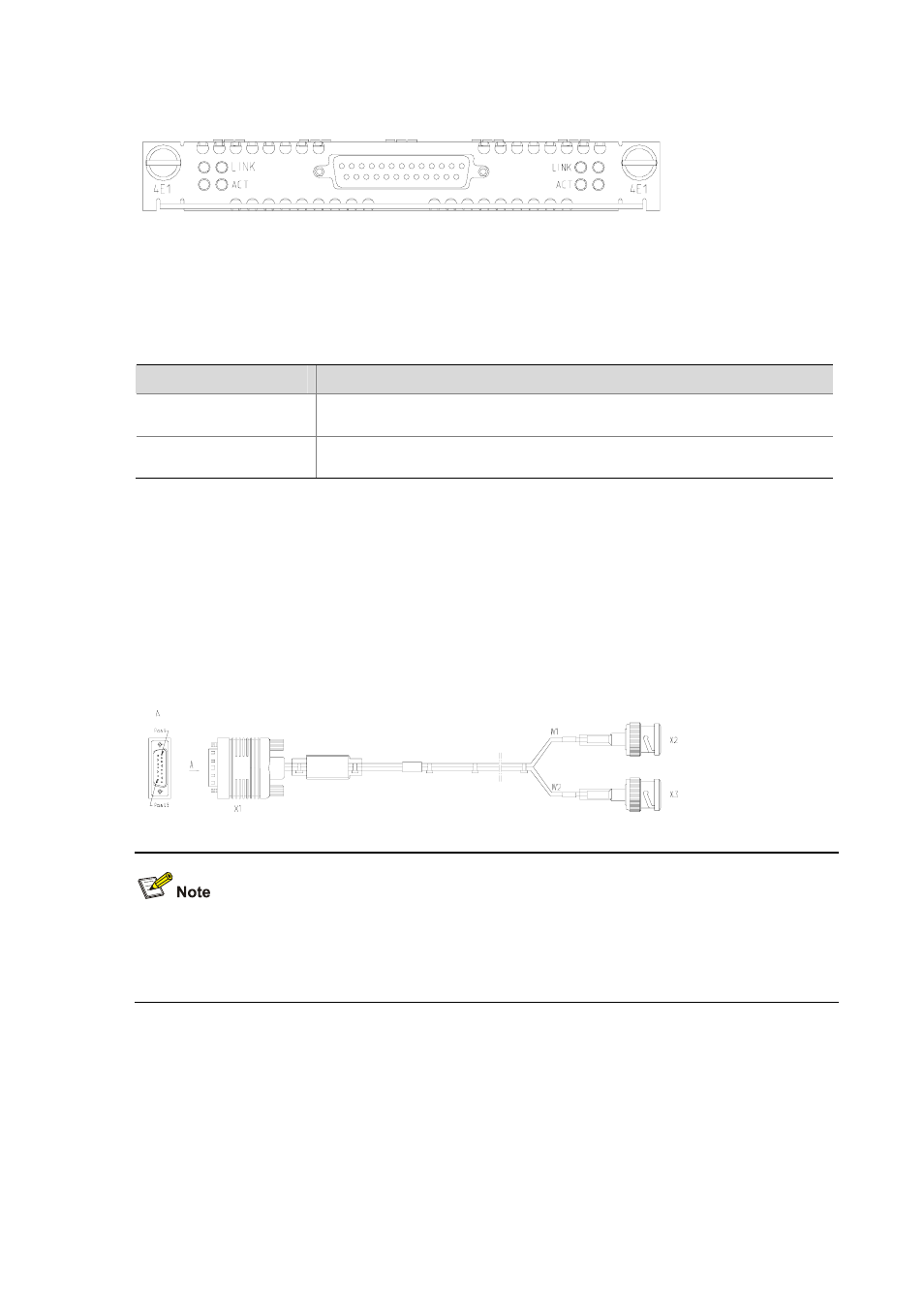
Figure 3-36 MIM-4E1 panel
cE1/PRI
0
1
2
3
The following table describes the LEDs on MIM-1E1/MIM-2E1/MIM-4E1 and
MIM-1E1-F/MIM-2E1-F/MIM-4E1-F panels:
Table 3-31 Description of the LEDs on MIM-1E1/MIM-2E1/MIM-4E1 and
MIM-1E1-F/MIM-2E1-F/MIM-4E1-F panels
LED
Description
LINK
z
ON means the carrier signal has been received.
z
OFF means no carrier signal has been received.
ACTIVE
z
OFF means no data is being transmitted or received.
z
ON means data is being transmitted or received.
Interface cable
1) Interface cable of MIM-1E1/MIM-2E1 and MIM-1E1-F/MIM-2E1-F modules
MIM-1E1/MIM-2E1 and MIM-1E1-F/MIM-2E1-F interface cables are G.703-compliant cables (referred
to as E1 cables throughout the rest part of the manual). E1 cables are divided into two types: 75-ohm
unbalanced coaxial cables and 120-ohm balanced twisted pair cables.
z
75-ohm unbalanced coaxial cable
Figure 3-37 E1 75-ohm unbalanced coaxial cable
You can select a pair of coaxial connectors with a BNC receptacle at both ends that connect two
75-ohm unbalanced coaxial cables with BNC connectors. The coaxial connectors are used for the
extension connection with E1 75-ohm unbalanced coaxial cable.
z
120-ohm balanced twisted pair cable
At the router side, the connector of the cable is DB-15 (male); at the network side, the connector is
RJ-45, as illustrated in the following figure.